Device used to study ion photoexcitation product

A technology of photoexcitation and after-product, applied in the direction of ion source/gun, parts of particle separator tube, particle separation tube, etc., can solve the problem of inability to detect delayed emission electrons, etc., and achieve the effect of high ion density

Active Publication Date: 2017-12-22
TIANJIN AIKETE MEASUREMENT CONTROL TECH
View PDF4 Cites 3 Cited by
  • Summary
  • Abstract
  • Description
  • Claims
  • Application Information

AI Technical Summary

Problems solved by technology

[0003] In some polyatomic anion systems, according to the non-adiabatic coupling, the electron energy obtained by photoexcitation is distributed according to its vibration degree of freedom; when the vibration energy is reconverted into electron energy, the electron is emitted from the system. This process is relatively The process of photoexcitation has a delay on the order of microseconds. However, the defect of the existing technology is that in most existing photoelectron spectroscopy experiments, only the experimental data related to the instant electron emission can be obtained, but the delay cannot be detected. Emit electrons and obtain their related information, the device for studying the products after ion photoexcitation can solve the problem

Method used


Image

  • Device used to study ion photoexcitation product

Examples


Embodiment Construction

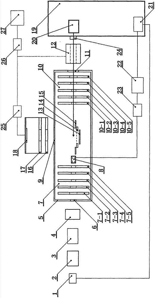
[0027] Such as figure 1 It is a structural schematic diagram of the present invention, mainly including ion source (1), accelerator (2), time-of-flight mass spectrometer (3), particle mass selector (4), magnetic shield (5), ion beam inlet (6), composed of electrodes I (7-1), electrode II (7-2), electrode III (7-3), electrode IV (7-4), electrode V (7-5) composed of focusing electrode group (7), cluster electrode ( 8), photoelectron outlet (9), composed of electrode VI (10-1), electrode VII (10-2), electrode VIII (10-3), electrode IX (10-4), electrode X (10-5) The mass selection electrode group (10), ion outlet (11), ion detector (12), electron background reduction plate (13), reflector plate (14), ion correction plate (15), extraction electrode (16), poly Beam electrode (17), electron detector (18), laser (19), regenerative amplifier (20), fiber optic oscillator (21), FPGA (22), signal generator (23), optical signal delay unit (24) , an electrical signal delay unit (25), a co...


PUM


Abstract

The invention relates to the field of optoelectronics and molecular reaction kinetics, and provides a device used to study an ion photoexcitation product. The device comprises an ion source, an accelerator, a flight time mass spectrum, a particle mass selector, a magnetic shield, an ion beam inlet, a focusing electrode set, a beam concentration electrode, a photoelectron exit, a mass selection electrode set, an ion exit, an ion detector, an electronic background reducing plate, a reflection plate, an ion correction plate, an extraction electrode, a beaming electrode, an electron detector, a laser, a regenerative amplifier, an optical fiber oscillator, an FPGA, a signal generator, an optical signal delay unit, an electrical signal delay unit, a coincidence unit, a computer and a cable. The beam concentration electrode, the reflection plate, the ion correction plate, the extraction electrode and the beaming electrode are all annular. The electronic background reducing plate, the reflection plate, the ion correction plate and the beam concentration electrode are arranged in sequence and located between the focusing electrode set and the mass selection electrode set. Metal meshes are arranged in the holes of five electrode centers of the focusing electrode set and the mass selection electrode set.

Description

technical field [0001] The invention relates to the field of optoelectronic imaging technology and molecular reaction dynamics, in particular to a method for researching products after ion photoexcitation, which can simultaneously perform imaging of electrons and ion fragments, and has the ability to detect instantaneously emitted electrons and delayed emitted electrons. device. Background technique [0002] Particle velocity imaging technology is an important method for the study of molecular reaction dynamics. Its most important feature is that it can obtain the full three-dimensional velocity and direction distribution of scattering particles in one image at the same time, that is, it can simultaneously obtain the energy spectrum of particles. information and angular distribution information. Particle velocity imaging techniques can be applied in simultaneous measurements of photodissociation, where photodissociation of electrons in steady-state molecular anions produces...

Claims


Application Information

Patent Timeline
Patent Type & Authority Applications(China)
IPC IPC(8): H01J49/10H01J49/00H01J49/40
CPCH01J49/0045H01J49/10H01J49/40
Inventor 黄惠民张向平赵永建
Owner TIANJIN AIKETE MEASUREMENT CONTROL TECH
Why Eureka
Try Eureka