
Tool-type U-shaped fixing tool for anti-floating anchor steel bars

A technology for anti-floating anchor rods and fixing tools, which is applied in the direction of foundation structure engineering, sheet pile walls, protection devices, etc., can solve the problems of welding quality hidden dangers, anchor rod steel bar corrosion hidden dangers, high site requirements, etc., and achieve convenient on-site operation and security Construction quality, the effect of premium construction quality

Inactive Publication Date: 2017-12-19
CHINA CONSTR THIRD ENG BUREAU GRP CO LTD
View PDF4 Cites 1 Cited by
  • Summary
  • Abstract
  • Description
  • Claims
  • Application Information

AI Technical Summary

Problems solved by technology

[0003] Although this method can fix the anchor bar and control the distance of the protective layer to a certain extent, there are four problems: first, the distance between the anchor bars cannot be effectively guaranteed, and it is easy to cause the gap between the anchor bars and steel bars due to human factors. The distance between the protective layers is too small, so that the single anchor hole cannot bear the force as a whole, which affects the anti-floating effect; the second is welding on the anchor reinforcement, which weakens the anchor reinforcement to a certain extent; the third is that the surface of the reinforcement is at the position of the weld The waterproof paint cannot be effectively applied, and there are hidden dangers of corrosion of the anchor rod reinforcement; Fourth, the welding process has high requirements on the site. If the anchor rod is required to be extended vertically during the hole drilling process due to site restrictions, the welding efficiency will be greatly reduced and the welding quality will be seriously affected. Hidden danger

Method used


Image

  • Tool-type U-shaped fixing tool for anti-floating anchor steel bars
  • Tool-type U-shaped fixing tool for anti-floating anchor steel bars
  • Tool-type U-shaped fixing tool for anti-floating anchor steel bars

Examples


Embodiment Construction

[0015] The following will clearly and completely describe the technical solutions in the embodiments of the present invention with reference to the accompanying drawings in the embodiments of the present invention. Obviously, the described embodiments are only some, not all, embodiments of the present invention. Based on the embodiments of the present invention, all other embodiments obtained by persons of ordinary skill in the art without making creative efforts belong to the protection scope of the present invention.

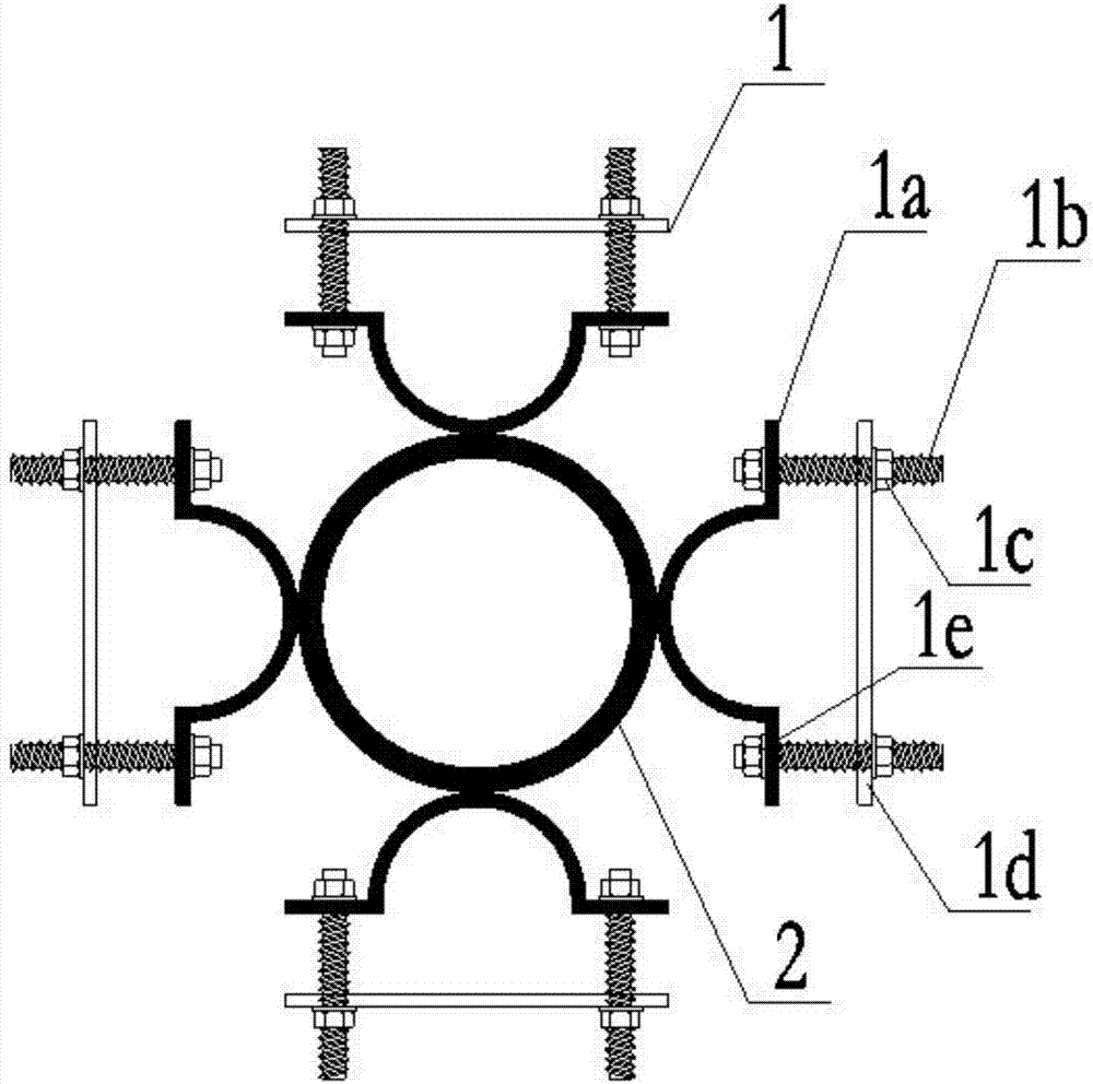
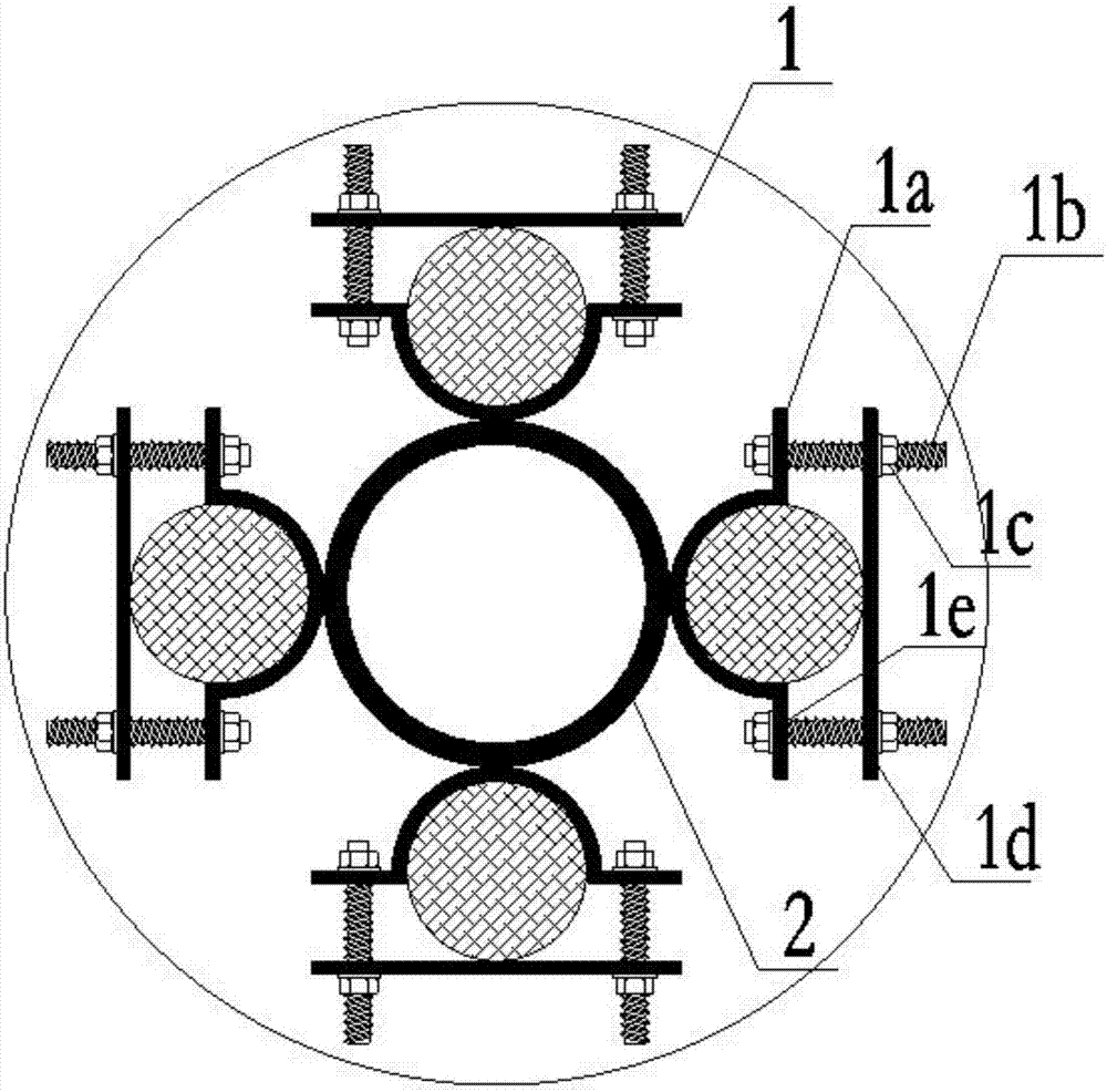
[0016] see Figure 1~3 , a tool-type U-shaped anti-floating bolt reinforcement fixing tool, including a U hoop 1 and a connecting pipe 2, the U hoop 1 is composed of a U-shaped ring 1a, a bolt 1b, a nut 1c, a flat iron 1d, and a gasket 1e; the U hoop 1. Two bolt holes are pre-drilled on the flat iron plate 1d; the bolt 1a passes through the gasket 1e, the U-shaped ring 1a, the flat iron plate 1d, the gasket 1e, and the nut 1c in order to fix it, and the U hoop...


PUM


Abstract

The invention discloses a tool-type U-shaped fixing tool for anti-floating anchor steel bars. The tool-type U-shaped fixing tool for the anti-floating anchor steel bars comprises U-shaped hoops and a connecting pipe. Each U-shaped hoop is composed of a U-shaped ring, bolts, nuts, a flat iron plate and pads, wherein two bolts hole are pre-drilled in the U-shaped hoop 1 and the flat iron plate, and the bolts penetrate through the pads, the U-shaped ring, the flat iron plate, another pads and the nuts sequentially to be fixed. The U-shaped hoops and the connecting pipe are welded and assembled together. According to the tool-type U-shaped fixing tool for the anti-floating anchor steel bars, the design is reasonable, machining and manufacturing are easy, convenient and fast, field operation is convenient and simple, the anti-floating anchor steel bars can be fixed efficiently and accurately, the distance of protection layers of the anti-floating anchor steel bars is effectively controlled without affecting coating of surface waterproof paint of anti-floating anchors, the construction quality of an anti-floating anchor project can be well guaranteed, the anti-floating safety of a main structure is ensured, meanwhile, the tool-type U-shaped fixing tool is adaptable to various construction environments, and the construction efficiency of both transverse butt joint and vertical butt joint can be ensured; and besides, the quality of the tool is ensured after the tool is shaped, and the tool can be produced and machined on a large scale as an industrial product.

Description

technical field [0001] The invention relates to the technical field of construction engineering, in particular to a tool-type U-shaped anti-floating anchor bar fixing tool. Background technique [0002] In foundation and foundation engineering, the construction quality of the anti-floating anchor is related to the overall safety performance of the main structure. In the construction process of the anti-floating anchor, the fixing of the steel bar and the control of the distance of the protective layer are particularly important. The existing anti-floating anchor fixing measures are usually: welding the anchor to the connecting sleeve (usually a small piece of seamless steel pipe) in advance, so as to fix the anchor reinforcement and control the protective layer distance between the anchor reinforcement. function, and then weld the positioning reinforcement on the anchor reinforcement to control the protection distance between the anchor reinforcement and the anchor hole. ...

Claims


Application Information

Patent Timeline
Patent Type & Authority Applications(China)
IPC IPC(8): E02D5/74E02D31/12
CPCE02D5/74E02D31/12E02D2300/0029E02D2600/20
Inventor 任志平张今虎雷展奇彭伟罗贵军施圣贤董进王泽语
Owner CHINA CONSTR THIRD ENG BUREAU GRP CO LTD
Learn More