Conductive graphite smearing device for cable detection
A technology of conductive graphite and cables, which is applied in the direction of measuring devices, devices for coating liquid on the surface, and parts of electrical measuring instruments, etc., can solve problems such as air pollution and health hazards of workers, and prevent random movement, The effect of avoiding waste of resources
- Summary
- Abstract
- Description
- Claims
- Application Information
AI Technical Summary
Problems solved by technology
Method used
Image
Examples
Embodiment 1
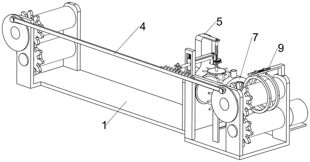
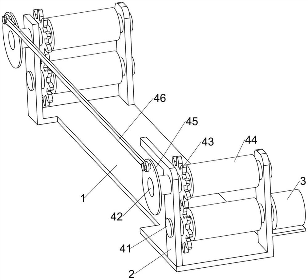
[0028] A conductive graphite smearing device for cable detection, such as Figure 1-9 As shown, it includes a base plate 1, a support plate 2, a slow motor 3, a cable conveying assembly 4, an annular rotation assembly 5 and a graphite liquid application assembly 6, the support plate 2 is fixed on the top of one side of the base plate 1, and the slow motor 3 is installed on On the top of the bottom plate 1 side away from the support plate 2, the slow motor 3 is used to drive the power shaft 41 connected thereto and the upper device to rotate slowly. Conveying the cable, the annular rotating assembly 5 is arranged on the base plate 1, and the graphite liquid smearing assembly 6 is arranged on the annular rotating assembly 5, and through the mutual cooperation of the cable conveying assembly 4, the annular rotating assembly 5 and the graphite liquid applying assembly 6, the Liquid graphite is evenly and fully applied to the cable wire.
[0029] The cable conveying assembly 4 inc...
Embodiment 2
[0034] On the basis of Example 1, such as Figure 5-7 As shown, when the liquid graphite is not enough, it also includes a graphite liquid replenishment assembly 7, the graphite liquid replenishment assembly 7 is arranged on the base plate 1, and the graphite liquid replenishment assembly 7 is used to replenish liquid graphite for the staff to pass through conveniently, and the graphite liquid replenishment assembly 7 It includes a fixed seat 71, an annular hollow frame 72, a connecting ring 73 and a connecting pipe 74. The fixed seat 71 is fixed on the top of the bottom plate 1. The fixed seat 71 is used to support the annular hollow frame 72 and its upper device. The annular hollow frame 72 is fixedly connected to the upper part of the fixed seat 71, and the connecting ring 73 is slidably arranged in the annular hollow frame 72. Through the mutual cooperation of the annular hollow frame 72 and the connecting ring 73, the liquid graphite poured from the connecting pipe 74 can ...
Embodiment 3
[0037] On the basis of Example 2, such as Figure 5 As shown, it also includes a graphite liquid collection assembly 8, the graphite liquid collection assembly 8 is located on the fixed seat 71, the graphite liquid collection assembly 8 is used to collect the liquid graphite that flows out too much and reuses to avoid waste of resources, the graphite liquid collection The assembly 8 includes a collection frame 81 and an output pipeline 82. The middle part of the fixing seat 71 is fixedly connected with the collection frame 81, and the bottom of the collection frame 81 is fixedly connected with the output pipeline 82. Through the mutual cooperation of the collection frame 81 and the output pipeline 82, excessive The outflowing liquid graphite can be reused to avoid waste of resources.
[0038] When the liquid graphite flows from the smearing groove block 63 to the cable, it is easy to flow out too much, resulting in waste. Through the mutual cooperation of the collection frame ...
PUM
 Abstract
Description
Claims
Application Information
 - R&D
- Intellectual Property
- Life Sciences
- Materials
- Tech Scout
- Unparalleled Data Quality
- Higher Quality Content
- 60% Fewer Hallucinations
Browse by: Latest US Patents, China's latest patents, Technical Efficacy Thesaurus, Application Domain, Technology Topic, Popular Technical Reports.
© 2025 PatSnap. All rights reserved.Legal|Privacy policy|Modern Slavery Act Transparency Statement|Sitemap|About US| Contact US: help@patsnap.com


