Radar component package and manufacturing method thereof

A package and radar technology, used in semiconductor/solid-state device manufacturing, measurement devices, electrical components, etc., can solve the problems of excessively long line length, large component thickness, and reduced thickness, and achieve reduction in line length, thickness, and thickness. Loss reduction effect

Active Publication Date: 2019-10-18
NAT CENT FOR ADVANCED PACKAGING CO LTD
View PDF9 Cites 0 Cited by
  • Summary
  • Abstract
  • Description
  • Claims
  • Application Information

AI Technical Summary

Problems solved by technology

However, the disadvantage of this packaged radar transceiver assembly is that it uses wire bonding to arrange the chips, which not only causes the length of the line to be too long and thus causes a large loss, but also needs to reserve a certain height in the box for wire bonding. bonded wires, resulting in a larger thickness of the component
In addition, the manufacture of the packaged radar transceiver component adopts the traditional packaging process including patching, wire bonding, and substrate manufacturing steps, so that the thickness of the substrate and chip limits the further reduction of the thickness of the component

Method used


Image

  • Radar component package and manufacturing method thereof
  • Radar component package and manufacturing method thereof
  • Radar component package and manufacturing method thereof

Examples


Embodiment Construction

[0043] It should be noted that components in the various figures may be shown exaggerated for the purpose of illustration and are not necessarily true to scale. In the various figures, identical or functionally identical components are assigned the same reference symbols.

[0044] Unless otherwise specified, in this application, the quantifiers "a" and "an" do not exclude the scene of multiple elements.

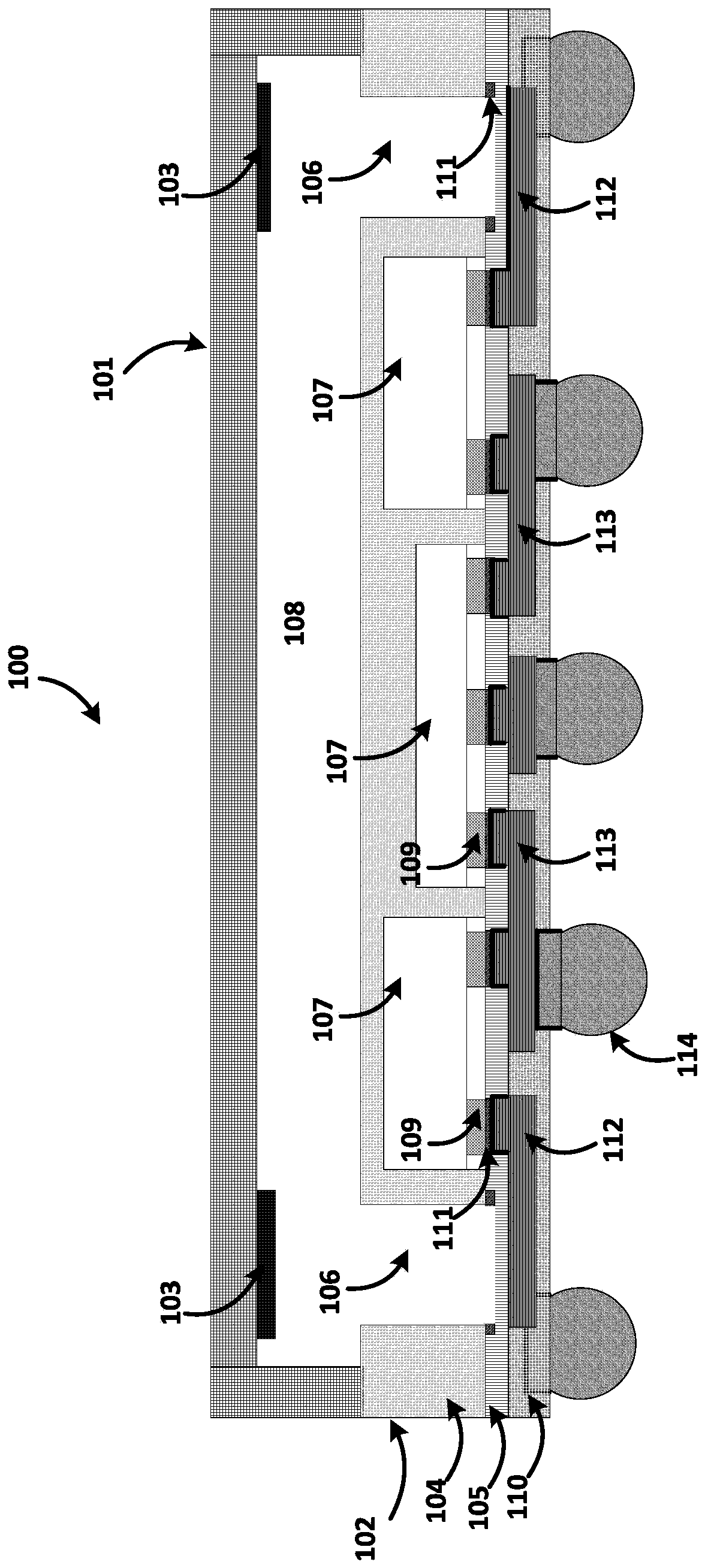
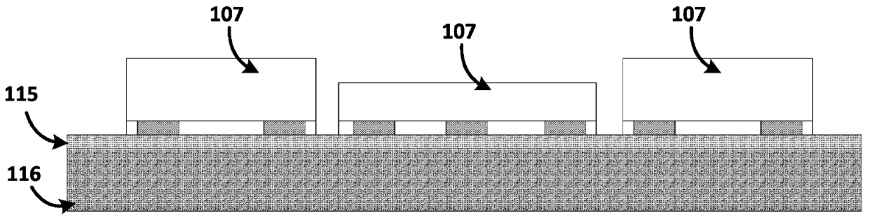
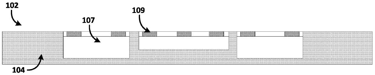
[0045] figure 1 A schematic diagram of a radar component package 100 according to the present invention is shown.

[0046] Such as figure 1 As shown, the radar component package 100 according to the present invention includes a box cover 101 and a box body 102 .

[0047]The case cover 101 may be made of a material with a low dielectric constant, such as polytetrafluoroethylene. On the inner wall of the lid 101 is arranged a metal layer 103 made of, for example, titanium, copper, nickel, tungsten, silver, gold or alloys thereof. By arranging the metal layer 103, the hole ...


PUM


Abstract

The present invention relates to a radar component packaging body, comprising: a case cover, which has a metal layer arranged on the inner surface of the case cover, wherein a cavity is formed between the case cover and the case body; and a case body, which has: An insulator, which is connected to the box cover, wherein a hole is opened in the first insulator, one end of the hole corresponds to the position of the antenna and the other end communicates with the cavity; one or more chips, the chip is flip-chip arranged on the second insulator and covered by the first insulator; the second insulator; the third insulator; and the antenna and the conductive line, the antenna and the conductive line are arranged in the third insulator and pass through the soldering of the second insulator and the chip A pad connection, wherein a metal barrier layer is arranged between the antenna and the pad and between the conductive line and the pad, respectively, and the conductive line is exposed from the third insulator for electrical contact. The invention also relates to a method of manufacturing the package.

Description

technical field [0001] The present invention relates generally to the field of semiconductor manufacturing, and in particular to a radar component package and a method for manufacturing such a radar component package. Background technique [0002] As the functions of consumer products become more and more diverse, there is a need for wireless detection (such as detection of moving objects and their speed) in many fields such as automobiles, robots and smartphones, so the application of radar components is increasing. However, applications in many fields, such as smartphones, balloons, airships, etc., impose strict requirements on the size and weight of radar components, so technicians have been trying to improve the integration of radar component packages to reduce its weight and size. [0003] From the Chinese patent application 201510149446.5 titled "A device for four-sided flat leadless packaged radar transceiver assembly", a packaged radar transceiver assembly is disclo...

Claims


Application Information

Patent Timeline
Patent Type & Authority Patents(China)
IPC IPC(8): G01S7/02G01S7/28H01L25/16H01L23/66H01L23/31H01L21/50
CPCG01S7/02G01S7/28G01S7/027H01L21/50H01L23/3107H01L23/66H01L25/16H01L2223/6677H01L21/568H01L2224/04105H01L2224/12105H01L2224/19H01L2224/24137H01L2224/96
Inventor 张文奇陈峰
Owner NAT CENT FOR ADVANCED PACKAGING CO LTD
Why Eureka
Try Eureka