
Electronic automatic pallet device

A pallet and electronic technology, applied in conveyor control devices, transportation and packaging, conveyor objects, etc., can solve the problems of destroying product quality, increasing labor costs, safety accidents, etc., to ensure product quality, improve production efficiency, and save money. The effect of labor cost

Inactive Publication Date: 2017-12-15
XUCHANG UNIV
View PDF6 Cites 4 Cited by
  • Summary
  • Abstract
  • Description
  • Claims
  • Application Information

AI Technical Summary

Problems solved by technology

[0003] 1. Using manual and forklift machinery to transport semi-finished products requires special personnel to operate, which increases labor costs. During the transfer process, due to shaking and bumps, it is very easy to cause collisions between semi-finished products, which seriously damages the quality of the product.
[0004] 2. The way of belt transmission requires the next-order processing personnel to pick up the semi-finished products at the end of the transfer to prevent the semi-finished products from colliding, which is easy to distract the attention of the processing personnel, affect production efficiency, and cause safety accidents. The manual handling and placement of semi-finished products by subsequent operators will also cause semi-finished products Collisions between products destroy product quality

Method used


Image

  • Electronic automatic pallet device
  • Electronic automatic pallet device
  • Electronic automatic pallet device

Examples


Embodiment approach

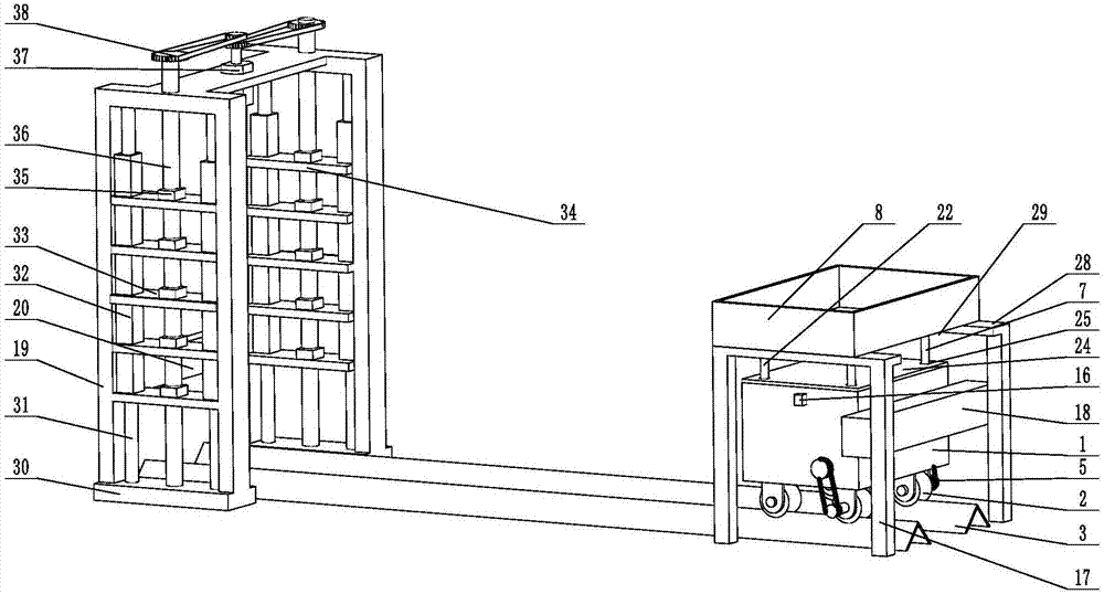
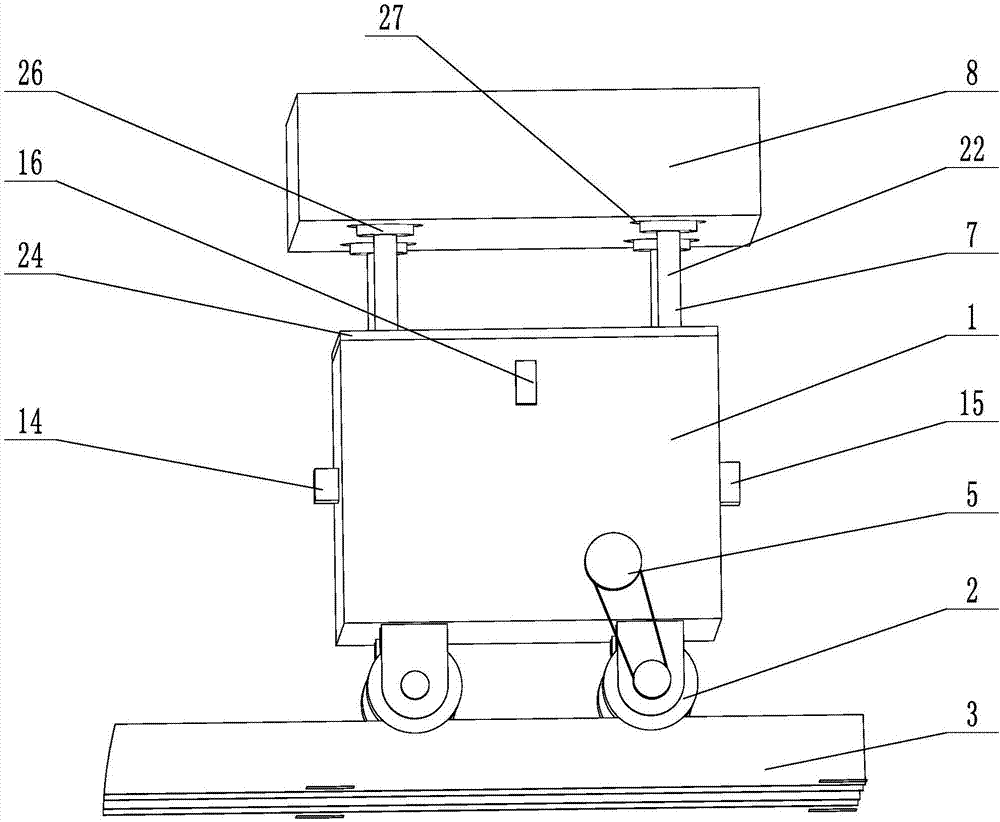
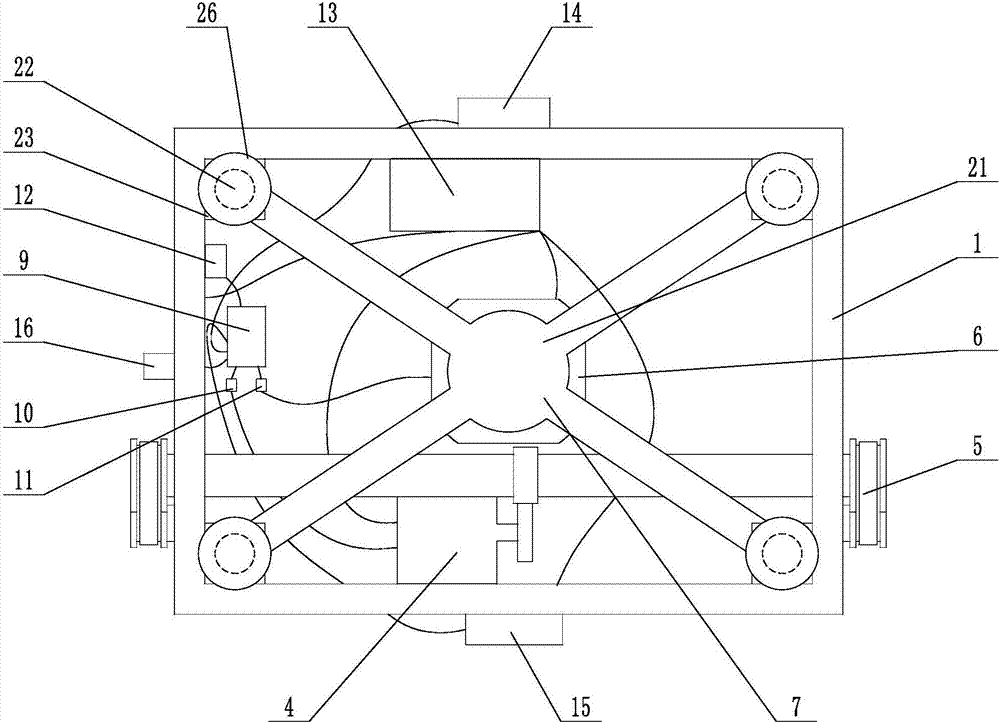
[0033] When the present invention is in use, the initial position of the present invention is at the bottom of the rack 17, and the inner contour of the rack 17 is compatible with the outer contour of the housing 1, and a rack 8 is placed above the rack, and the bottom of the rack 8 is in contact with the lifting device 7. The lifting device 7 is now in a raised state, and supports the storage board 8 . The storage board 8 is used to place the processed semi-finished products. After the semi-finished product is placed on the storage board 8, the operator touches the third travel switch 16, and the third travel switch 16 transmits the signal to the single-chip microcomputer 9, and the single-chip microcomputer 9 processes the signal and controls the first motor 4 through the first motor drive module 10 Running, the first motor 4 drives the wheel set 2 to advance on the track 3 through the first transmission device 5. When the device moves to the key point of the track 3, that i...

Embodiment

[0035] The electronic automation tray device includes a housing 1, which can be made of hard plastic or metal. In this embodiment, metal plates are welded and formed. In this embodiment, the housing is in the shape of a cuboid. The bottom of the housing 1 is provided with a wheel set 2. In this embodiment, the wheel set includes two pairs of wheels, and the two pairs of wheels are arranged opposite to each other. The middle part of the outer profile of the wheel is provided with an annular groove, the bottom of the wheel set 2 is provided with a track 3, and the track 3 is fixed on the ground, and the height of the track 3 is lower than the ground level. In this embodiment, the track 3 is made of two parallel undercut angle steels, and the track matches with the annular groove so that the wheels can rotate on the track. A first motor 4 is arranged on the bottom surface of the inner contour of the housing 1, and the first motor is fixed to the bottom of the housing by bolts, an...


PUM


Abstract

The invention provides an electronic automatic pallet device, and mainly relates to the field of material transferring equipment. The electronic automatic pallet device comprises a shell; a first motor is arrange on the bottom surface of the inner contour of the shell; an electric cylinder is arranged at the center of the bottom of the shell; a lifting device is arranged on the top of the electric cylinder; an object placement plate is arranged on the top of the lifting device; a single-chip computer is arranged on the bottom of the shell; a first motor driving module and a second motor driving module are arranged on the single-chip computer; a first direct-current power and a second direct-current power are arranged in the shell; a first journey switch is arranged on the front surface of the outer wall of the shell; a second journey switch is arranged on the rear surface of the shell; and a third journey switch is arranged on the top of the shell. The electronic automatic pallet device has the beneficial effects that labor cost can be reduced; and operation is stable; collision among semi-products can be effectively avoided during a transferring process, so that product quality is ensured.

Description

technical field [0001] The invention mainly relates to the field of material transfer equipment, in particular to an electronic automatic pallet device. Background technique [0002] The transfer of materials is an important link in the machining industry. Fast and efficient transfer of materials and semi-finished products between processes can effectively improve processing efficiency and product quality. The streamlined operation of the production line can effectively realize the transfer of materials and semi-finished products. However, in many processing industries, there is a large difference in processing time between the upper and lower processes. within the adjacent area. For example, small batches of non-standard fasteners cannot form a production line flow operation. In the processing of mechanical products that cannot form a production line, semi-finished products are usually transferred by manual handling, forklift transfer, belt transmission, etc. These methods...

Claims


Application Information

Patent Timeline
Patent Type & Authority Applications(China)
IPC IPC(8): B65G35/00B65G43/00
CPCB65G35/00B65G43/00
Inventor 于洋孙鹏牛书豪李文龙段敏杨枝茂张柯孟耀伟王奎甫翟广辉孙敬良
Owner XUCHANG UNIV
Learn More