Aluminum bar transferring device

A technology of transfer device and aluminum rod, which is applied in the direction of transportation and packaging, load hanging components, etc., can solve the problems of time-consuming and labor-intensive, and achieve the effect of saving operation and labor

Active Publication Date: 2016-05-18
佛山金兰铝厂有限公司
View PDF6 Cites 6 Cited by
  • Summary
  • Abstract
  • Description
  • Claims
  • Application Information

AI Technical Summary

Problems solved by technology

[0003] The present invention intends to provide an aluminum rod transfer device to solve the time-consuming and labor-intensive problem that it is necessary to manually put the ferrules on the aluminum rods one by one

Method used


Image

  • Aluminum bar transferring device
  • Aluminum bar transferring device

Examples


Embodiment Construction

[0014] The present invention will be described in further detail below by means of specific embodiments:

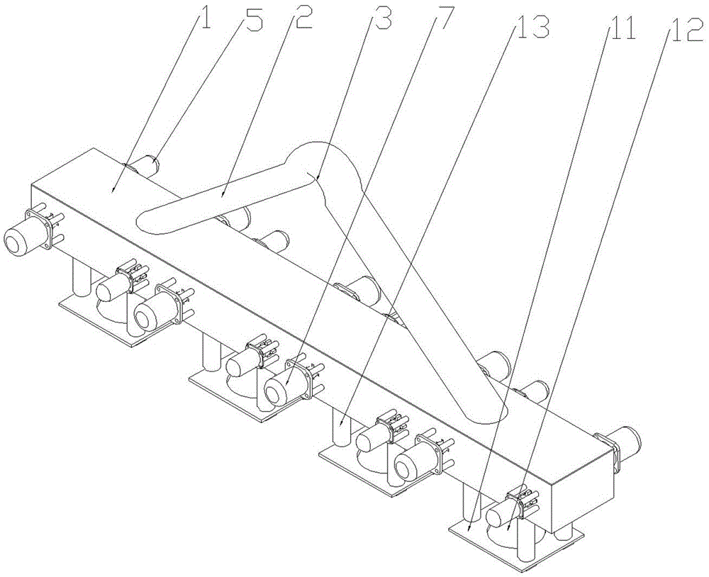
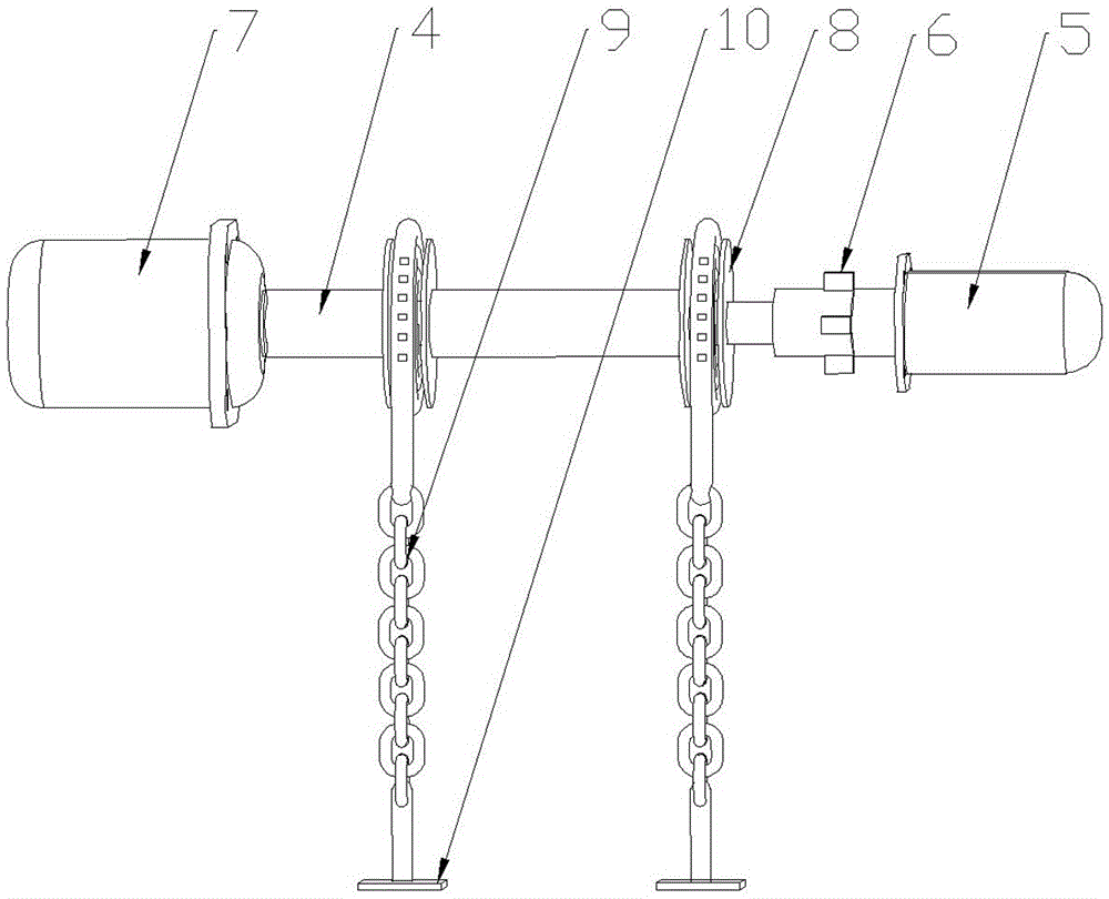
[0015] The reference signs in the drawings of the description include: transfer beam 1, lifting lug 2, arc section 3, rotating shaft 4, hydraulic column 5, cross block 6, motor 7, chain disc 8, chain 9, clip bar 10, sleeve Plate 11, round hole 12, cylinder 13.

[0016] Such as figure 1 with figure 2 Shown: An aluminum rod transfer device, including a transfer beam 1, the transfer beam 1 is provided with a lifting lug 2 for driving hooks, the transfer beam 1 is provided with a spare lifting lug 2, and the lifting lug 2 is provided with an arc section 3. The transfer beam 1 is provided with a through groove in the length direction, and the transfer beam 1 is provided with several rotating shafts 4 arranged in parallel in the width direction. The transfer beam 1 welds bearings for the rotating shaft 4 to pass through on both sides of the groove. The two ends of the rotat...


PUM


Abstract

The invention discloses an aluminum bar transferring device to solve the problem that ferrules need to be manually arranged on aluminum bars one by one in a sleeving manner at present, and time and labor are consumed. The aluminum bar transferring device comprises a transferring beam. A lifting lug used for being hooked and lifted by a travelling crane is arranged on the transferring beam. A through groove is formed in the transferring beam in the length direction. A plurality of rotating shafts which are arranged in parallel are arranged on the transferring beam in the width direction. Bearings for the rotating shafts to penetrate are arranged at the positions, on the two sides of the groove, of the transferring beam. A hydraulic pillar is arranged at one end of each rotating shaft, and a motor driving the corresponding rotating shaft to rotate is arranged at the other end of each rotating shaft. Two chain plates are fixedly arranged at the positions, on the inner side of the groove, of each rotating shaft. Chains are arranged on the chain plates. One end of each chain is fixedly arranged on the corresponding chain plate, and the other end of each chain is fixedly provided with a clamping bar. A sleeve plate is arranged below every two adjacent rotating shafts. Four openings used for the clamping bars to hook are evenly formed in the periphery of each sleeve plate. A round hole for an aluminum bar to penetrate is formed in the center of each sleeve plate. By means of the scheme, aluminum bars do not need to be manually sleeved, lifting and transferring are operated mechanically, time and labor are saved, and application and popularization are facilitated.

Description

technical field [0001] The invention belongs to the field of aluminum material processing equipment, and in particular relates to an aluminum bar transfer device. Background technique [0002] Now the aluminum rods are basically cast by the deep well casting system. The cast aluminum rods are arranged vertically in the deep well and need to be transferred to other places for subsequent processing. Now the transfer of aluminum rods generally uses several ferrules , There is a chain connected to the ferrule, and the chain is connected to a frame. The ferrules are placed on the aluminum rods one by one manually, and then the frame is lifted by the crane to move. Due to the inclination angle between the ferrule and the aluminum rod, The inside of the ferrule has a thrust on the aluminum rod. When the frame is lifted, the aluminum rod is inclined in the air, so there is friction between the two. Under the action of friction, the aluminum rod will not slip out of the ferrule. The...

Claims


Application Information

Patent Timeline
Patent Type & Authority Applications(China)
IPC IPC(8): B66C1/12
CPCB66C1/12
Inventor 何显平舒启燕
Owner 佛山金兰铝厂有限公司
Why Eureka
Try Eureka