
Array structure and realization method of MEMS electro-spray thruster

An array structure and thruster technology, applied in the field of electrospray thruster preparation, can solve the problems of inapplicability to micro-nano satellite applications, difficult array expansion, large volume and weight, etc., to achieve precise control tasks, simple composition and structure, and improved thrust The effect of the level of precision

Inactive Publication Date: 2017-12-15
BEIJING INST OF CONTROL ENG
View PDF9 Cites 7 Cited by
  • Summary
  • Abstract
  • Description
  • Claims
  • Application Information

AI Technical Summary

Problems solved by technology

[0004] The technical problem solved by the present invention is: to overcome the deficiencies of the prior art, to provide a MEMS electrospray thruster array structure and its implementation method, and to solve the problems of the existing traditional electrospray propulsion technology with large volume and weight, low integration and difficult array scaling, but not applicable to micro-nanosatellite applications

Method used


Image

  • Array structure and realization method of MEMS electro-spray thruster
  • Array structure and realization method of MEMS electro-spray thruster
  • Array structure and realization method of MEMS electro-spray thruster

Examples


Embodiment Construction

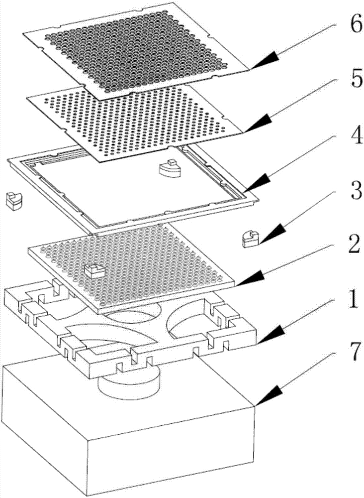
[0046] The invention provides a MEMS electrospray thruster array structure, which can be as figure 1 As shown, the structure is firstly explained below:

[0047] The MEMS electrospray thruster array structure provided by the present invention includes, from bottom to top, an installation base 1, an emitter 2, a positioning and insulating layer 3, an electrode installation frame 4, an extraction pole 5, an acceleration pole 6, and a storage tank 7 ; The emitter 2 is placed in the middle of the installation base 1, and is bonded by epoxy resin; the positioning and insulating layer 3 is located at the four corners of the installation base 1, and is bonded to the installation base 1, electrically isolating the described The emitter 2 and the extractor 5; the electrode mounting frame 4 and the positioning and insulating layer 3 are aligned and then bonded; the extractor 5 and the accelerating pole 6 are placed on the electrode mounting frame 4 in sequence, and the extracting pole 5...


PUM

PropertyMeasurementUnit
thicknessaaaaaaaaaa
thicknessaaaaaaaaaa

Abstract

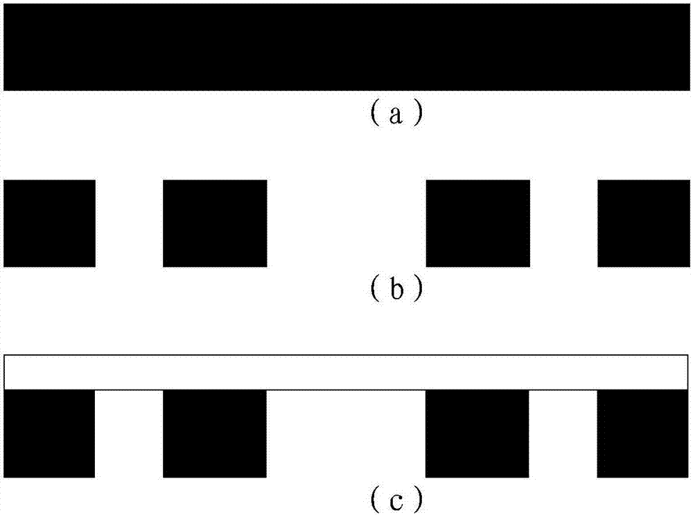
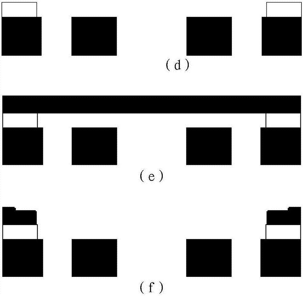
The invention provides an array structure and a realization method of an MEMS electro-spray thruster. The realization method comprises the following steps that 101, deep silicon etching and wet etching are conducted on a silicon wafer to obtain a mounting base (1); 102, an emitter (2) is obtained by conducting electrochemical etching on porous materials; 103, the emitter (2) is bonded on the mounting base (1); 104, a positioning and insulation layer (3) is obtained through silicon-glass-silicon anode bonding, glass etching and deep silicon etching; 105, the positioning and insulation layer (3) is bonded and connected to four corners of the mounting base (1) through an epoxy resin; 106, an electrode mounting frame (4) is obtained through deep silicon etching and wet etching conducted on the silicon wafer, and the electrode mounting frame (4) is bonded to the positioning and insulation layer (3) through the epoxy resin; 107, an extracting pole (5) and an accelerating pole (6) are obtained by conducting metal sputtering and electroplating on silicon based materials; and 108, a storing tank (7) storing propellants is connected with the emitter (2) through a boss on the storing tank (7).

Description

technical field [0001] The invention belongs to the field of electrospray thruster preparation, and relates to a MEMS electrospray thruster array structure and a realization method. Background technique [0002] Micro-nano satellites are an important direction for the development of satellites in the future. Micro-nano satellites have the advantages of low cost, short development cycle, strong expansion capability, flexible launch methods, etc., and are small in size and flexible in action; Or fly in formation to perform more complex space missions. This year, it has attracted the attention of various space powers, and the number of launches has increased year by year. However, with the increase in the complexity of micro-nano-satellite missions and the increase in the design life in orbit, corresponding propulsion modules will be required to complete their attitude control and orbit-keeping tasks; on the other hand, as the number of micro-nano-satellites increases, the Sp...

Claims


Application Information

Patent Timeline
Patent Type & Authority Applications(China)
IPC IPC(8): B64G1/26B81C3/00B81B7/02
CPCB64G1/26B81B7/02B81C3/001B81B2207/053F03H1/0012
Inventor 耿金越魏福智刘旭辉龙军扈延林沈岩陈君毛威李栋吴耀武仝颖刚吴朋安周磊李胜军臧娟伟
Owner BEIJING INST OF CONTROL ENG
Learn More