Wire uncoiling machine

A pay-off machine and frame technology, which is applied in the direction of conveying filamentous materials, thin material processing, transportation and packaging, etc., can solve the problems of variable copper wire tension and inconsistent copper wire thinness, etc. Stability, good uniformity of copper wire drawing, and stable quality

Inactive Publication Date: 2017-12-12
蒙玛特(天津)铜业有限公司
View PDF0 Cites 8 Cited by
  • Summary
  • Abstract
  • Description
  • Claims
  • Application Information

AI Technical Summary

Problems solved by technology

[0005] The purpose of the present invention is to provide a pay-off machine, which aims to solve the problem of inconsistent copper wire thinning degree caused by the variable copper wire tension when the pay-off machine is unwound in the prior art

Method used


Image

  • Wire uncoiling machine
  • Wire uncoiling machine
  • Wire uncoiling machine

Examples


Embodiment Construction

[0015] The invention provides a wire pay-off machine. The invention has the advantages of simple structure, convenient use, stable wire pulling force, good copper wire thinning uniformity and stable quality.

[0016] The technical solutions in the embodiments of the present invention will be described clearly and in detail below in conjunction with the accompanying drawings in the embodiments of the present invention. Obviously, the described embodiments are only part of the embodiments of the present invention, not all of them. Based on the embodiments of the present invention, all other embodiments obtained by persons of ordinary skill in the art without making creative efforts belong to the protection scope of the present invention.

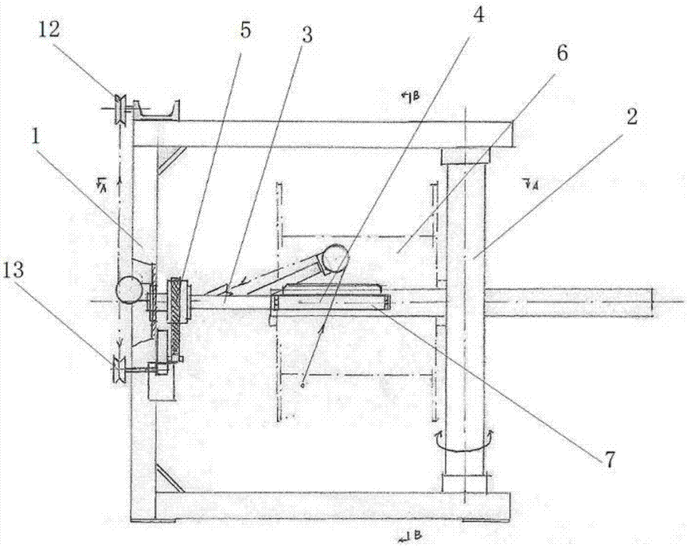
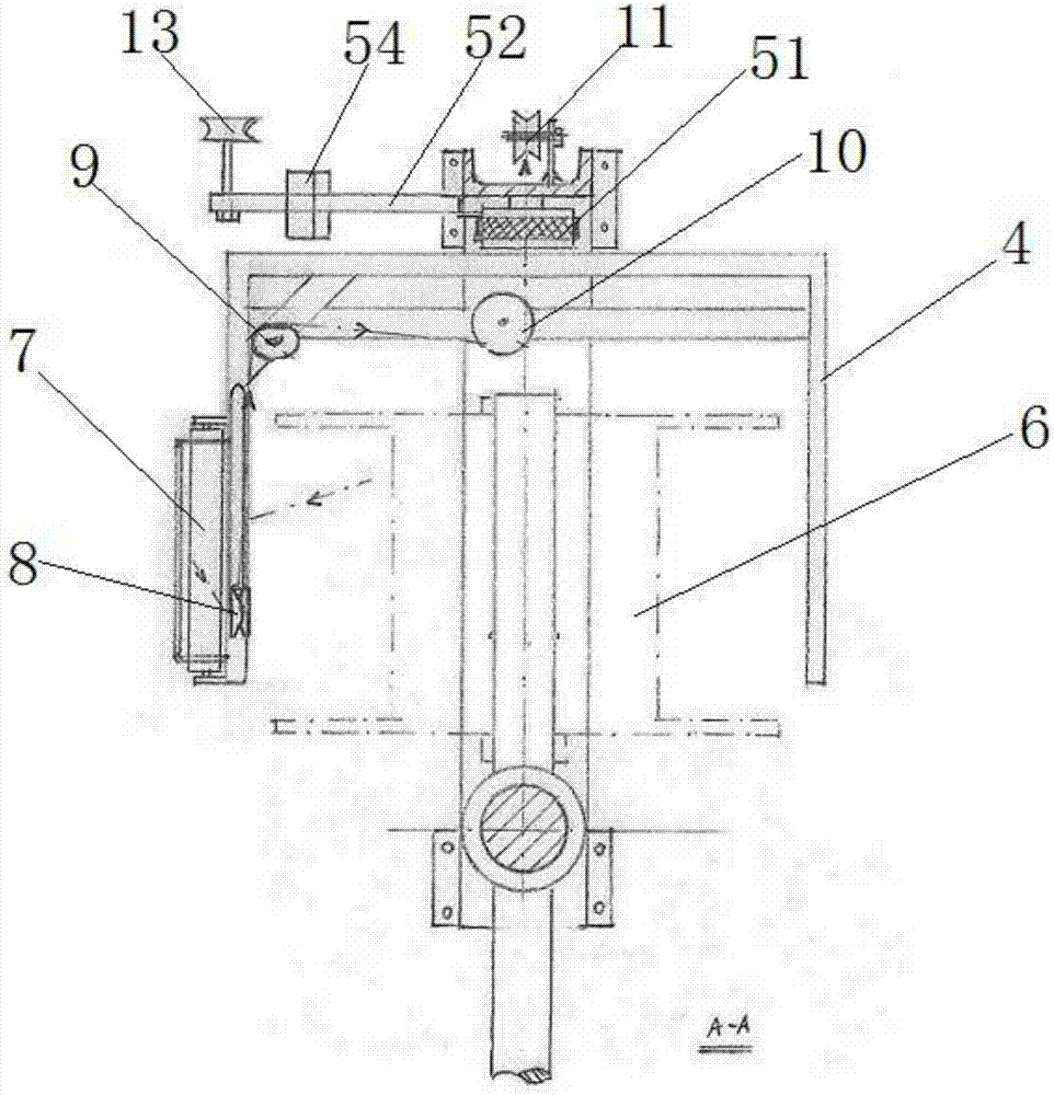
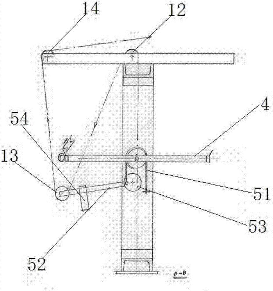
[0017] Such as Figure 1-3 A pay-off machine shown includes a frame 1, a vertical pole 2, a rotating shaft 3, a collar frame 4, a frictional resistance device 5, a wire wheel 6, a guide roller 7, a No. 1 guide wheel 8, and a No. 2 guide wheel ...


PUM


Abstract

The invention discloses a wire pay-off machine, one end of the frame is provided with a vertical rod, the middle part of the frame is horizontally provided with a rotating shaft, one end of the rotating shaft is installed on the frame, the other end of the rotating shaft is set on the middle part of the vertical rod, and a collar is arranged on the rotating shaft There is a guide roller on one side of the collar frame, a No. 1 guide wheel, a No. 2 guide wheel and a No. 3 guide wheel on the collar frame, and a No. Wheels and frictional resistance device, No. 5 guide wheel is set in the middle of the top of the frame, and No. 7 guide wheel is set at the top side of the frame. The frictional resistance device includes brake belt, brake lever, turntable, counterweight and No. 6 guide wheel. One end of the brake belt is fixed, and the other end goes around the shaft from the upper end and connects with the edge of the turntable. The connection point between the turntable and the brake belt is connected to one end of the brake lever. The other end of the brake lever is equipped with a No. 6 guide wheel. With a heavy hammer, the copper wire passes through the No. 1 to No. 7 guide wheels in sequence. The invention is convenient to use, has stable wire pulling force, good copper wire thinning uniformity and stable quality.

Description

technical field [0001] The invention relates to the technical field of cable production equipment, more specifically, to a pay-off machine. Background technique [0002] In the current technology, during the cable production process, the pay-off machine used is a central shaft type or an end shaft type rolling pay-off machine. When the wire pulls the reel to rotate and pay off, it can maintain a certain tension, which is the requirement of the stranding conductor process. [0003] The defect of this device is that due to the effect of the resistance device, a torque must be given to the wire wheel to make the wire wheel rotate. This torque is the tension multiplied by the radial distance from the center of the wheel to the copper wire. With the change of the radial position of the copper wire, the tension of the copper wire changes accordingly, the thinning degree of the copper wire is inconsistent, and the stability of the product quality is poor. [0004] Therefore, due ...

Claims


Application Information

Patent Timeline
IPC IPC(8): B65H49/32B65H59/36
CPCB65H49/32B65H59/36B65H2404/152
Inventor 邢彤
Owner 蒙玛特(天津)铜业有限公司
Why Eureka
Try Eureka