Cleaning device

A technology for cleaning and cleaning areas, applied in textile and paper making, paper machine, wet end of paper machine, etc., can solve the problems of environmental pollution and high energy consumption, and achieve the effect of reducing pollution and improving cleaning effect.

Inactive Publication Date: 2017-12-08
VOITH PATENT GMBH
View PDF10 Cites 1 Cited by
  • Summary
  • Abstract
  • Description
  • Claims
  • Application Information

AI Technical Summary

Problems solved by technology

This arrangement has the disadvantage that the mixture of cleaning medium and dirt must always be suctioned against the running direction of the conveyor belt
This requires a correspondingly high energy expenditure
Especially if the s

Method used


Image

  • Cleaning device
  • Cleaning device
  • Cleaning device

Examples


Embodiment Construction

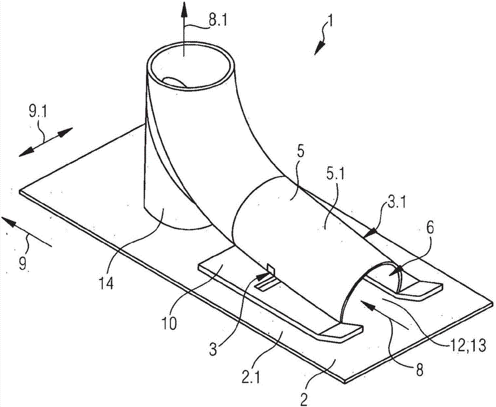
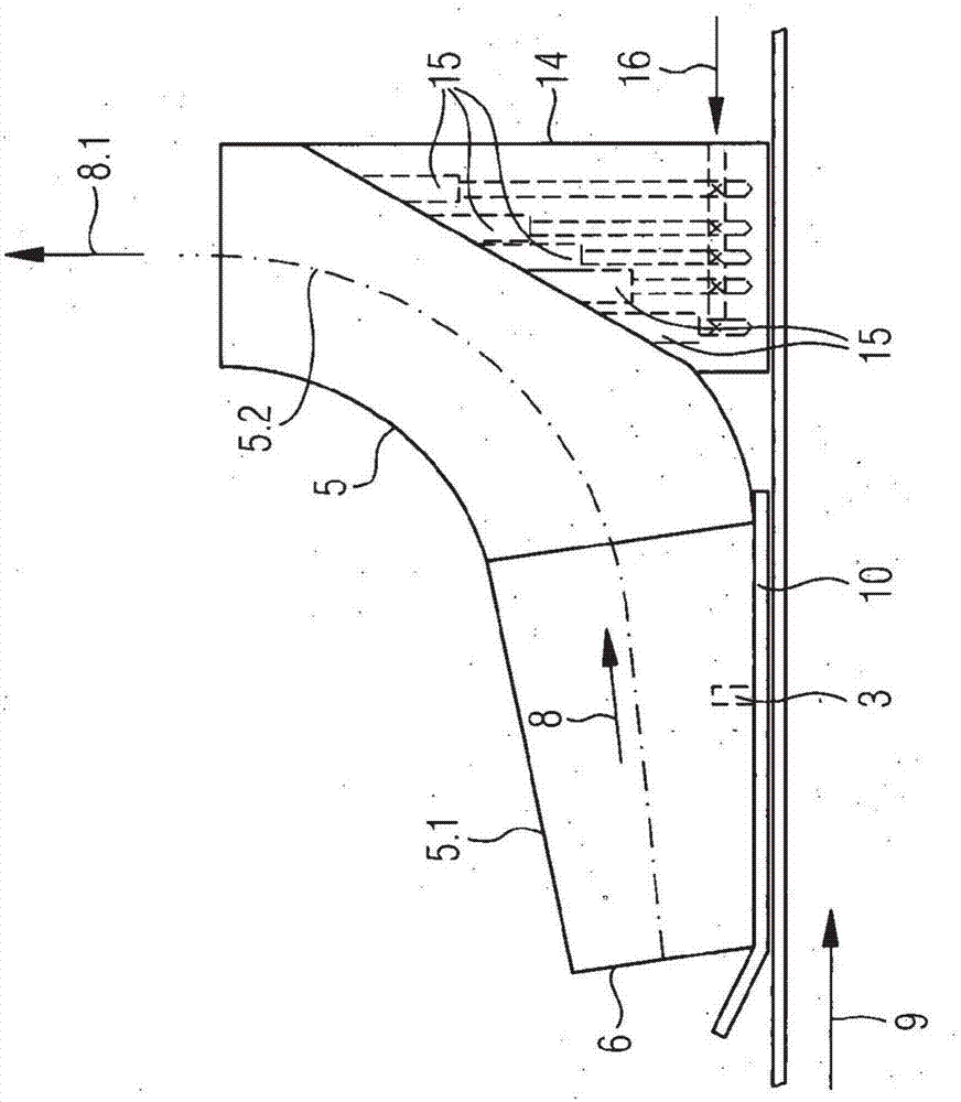
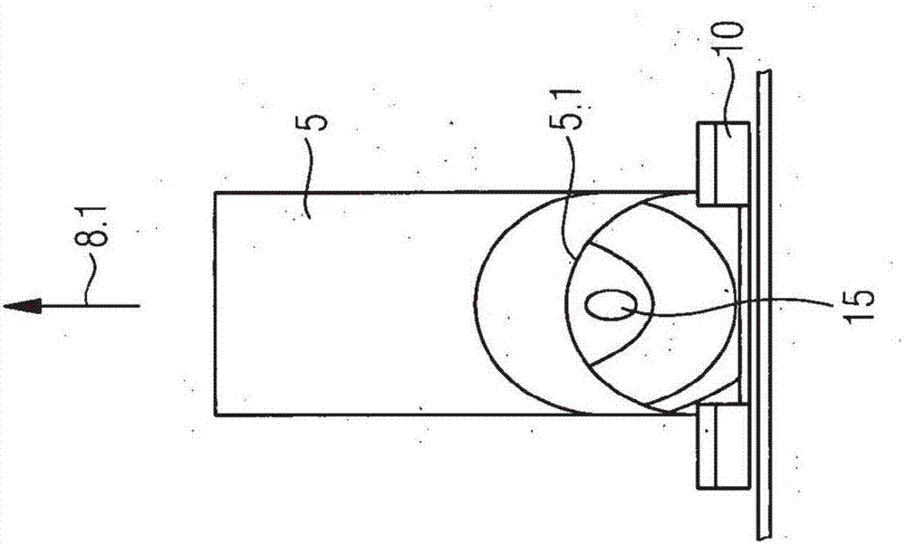
[0058] exist figure 1 The device 1 according to the invention is shown schematically and in perspective in FIG. The stretched wire 2 shown in fragments is a drying wire which runs around in the running direction 9 and is used for drying a fibrous web in the drying section of a paper machine. The device 1 is connected to a spanning device, not shown, and is moved back and forth in the transverse direction 9 . 1 continuously or at intervals during cleaning. Thus, the entire surrounding stretcher 2 , which spreads the stretcher plane 2 . 1 in the region of the device 1 , can be cleaned. The device 1 comprises a discharge channel 5 having a first section 5.1. It is made of a tube and therefore has no right-angled or sharp-angled corners on the inside. The tendency to contamination is therefore very small. The first section 5 . 1 has a receiving opening 6 . The device 1 is arranged relative to the drying wire 2 in such a way that the receiving opening 6 points opposite to the ...


PUM


Abstract

The invention relates to a device (1) for cleaning a continuously circulating fabric (2) in a paper machine for producing and/or processing a paper, cardboard, tissue or other fiber web, comprising at least one cleaning nozzle (3, 3.1), which generates at least one cleaning jet (4) from a fluid, said jet being directed towards the fabric (2), and comprising a discharge channel (5) for discharging the fluid and the dirt released from the fabric (2) by the cleaning jet (4) in a discharge direction (8). The discharge channel (5) has a first section (5.1) with a receiving opening (6) at the beginning of the discharge channel (5), said first section (5.1) of the discharge channel (5) having a cleaning opening (12) which faces the circulating fabric (2) and forms a cleaning zone (13), and the at least one cleaning nozzle (3, 3.1) is arranged such that the at least one cleaning jet (4) strikes the fabric (2) in the region of the cleaning zone (13). The device (1) according to the invention is characterized in that the receiving opening (6) is oriented opposite the running direction (9) of the circulating fabric (2) and in that the at least one cleaning nozzle (3, 3.1) is arranged such that the at least one cleaning jet (4) has a speed component in a transverse direction (9.1), thus transversely to the running direction (9) of the fabric (2), and strikes the fabric (2) in an angular range of 20 degrees < B < 80 degrees, in particular in an angular range of 30 degrees<B<70 degrees, with respect to the fabric plane (2.1) when viewed in the running direction (9) of the fabric.

Description

technical field [0001] The invention relates to a device for cleaning a stretched wire (Bespannung) which is continuously circulated in a paper machine for the production and / or processing of paper, cardboard or tissue or other fibrous material webs, which comprises the generation of at least one fluid At least one cleaning nozzle of the cleaning jet aimed at this stretching web and a discharge channel for the discharge of the fluid and the dirt detached from the stretching net by the cleaning jet in the discharge direction, wherein the discharge channel has a starting point at the discharge channel A first section with a receiving opening at , wherein the first section of the outlet channel has a cleaning opening pointing towards this surrounding stretcher and forming a cleaning zone, and at least one cleaning nozzle is arranged in such a way that At least one cleaning jet impinges on the stretched web in the region of the cleaning zone. [0002] The invention also relates t...

Claims


Application Information

Patent Timeline
IPC IPC(8): D21F1/32
CPCD21F1/32
Inventor 马克·霍德森卡尔海因茨·施特劳布
Owner VOITH PATENT GMBH
Why Eureka
Try Eureka