Electric push rod used for solar photo-thermal power generation

A technology of electric push rods and photothermal power generation, which is applied in the direction of electric components, circuits, electromechanical devices, etc., can solve the problems that electric push rods are prone to negative pressure, etc., and achieve the effects of improving service life, reducing energy consumption losses, and reducing burdens

Pending Publication Date: 2017-12-08
ZHEJIANG JIECHANG LINEAR MOTION TECH
View PDF18 Cites 0 Cited by
  • Summary
  • Abstract
  • Description
  • Claims
  • Application Information

AI Technical Summary

Problems solved by technology

[0005] The technical problem to be solved by the present invention is to overcome the deficiencies of the prior art and provide an electric push rod for solar thermal power generation, which can not only ensure the waterproof and dustproof effect of the electric push rod, but also solve the problem of negative pressure easily generated inside the electric push rod. The problem

Method used


Image

  • Electric push rod used for solar photo-thermal power generation
  • Electric push rod used for solar photo-thermal power generation
  • Electric push rod used for solar photo-thermal power generation

Examples


Embodiment 1

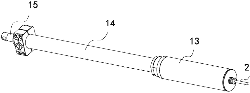
[0061] Such as Figure 1 to Figure 15 As shown, this embodiment shows an electric push rod for solar thermal power generation. This embodiment is mainly used in solar thermal power generation technology to drive heliostats. The electric push rod in this embodiment, its The main structure includes a motor 10, the motor 10 is connected with a drive screw 11, the drive screw 11 is connected with a nut 12, the motor 10 is installed in a base 13, the base 13 is fixedly connected with an outer tube 14, and the nut 12 is fixedly connected There is an inner tube 15. When the motor 10 drives the drive screw 11 to rotate, the nut 12 and the drive screw 11 move relative to each other. Specifically, it reciprocates between two positions on the drive screw 11. For the nut 12, it is Reciprocating motion between an initial position and limit positions. Overall, the relative movement between the inner tube 15 and the outer tube 14 is achieved, and the outermost end of the inner tube 15 is us...

Embodiment 2

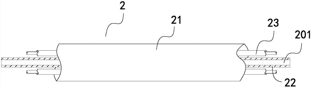
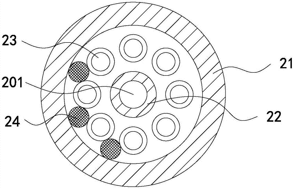
[0102] Such as Figure 16 As shown, the difference between this embodiment and Embodiment 1 is that there is no hollow conduit in this embodiment, and the core wire 23 inside the cable 2 in this embodiment includes a core wire sleeve 231, and the outside of the core wire sleeve 231 is provided with ribs 232, after the ribs 232 are set, the core wires 23 will not be tightly fitted, but a certain gap will be generated, and at the same time, a certain gap will also be generated between the core wire 23 and the inner wall of the sheath 21, and these gaps will naturally form The ventilation channel 201 .

Embodiment 3

[0104] The difference between this embodiment and Embodiment 1 is that there is no fixed seat in this embodiment, the photoelectric sensor is directly fixed on the base, and the touch panel is also installed on the base, and is installed in a sliding fit with the base. The structure is to set a chute on the base, let the touch plate slide and install in the chute, after the photoelectric sensor is installed on the base, cover it with a protective cover to prevent oil, of course, the protective cover is also set accordingly There is a first opening as in embodiment 1, for the trigger projection to stretch in or out.


PUM


Abstract

The invention discloses an electric push rod used for solar photo-thermal power generation, and belongs to the linear driving technical field. A motor is arranged in the electric push rod; the motor is in transmission connection with a transmission threaded rod; the rotation of the transmission threaded rod drives a nut to axially move relative to the transmission threaded rod; the electric push rod is characterized in that the motor is connected with a cable; the cable extends out of the electric push rod; the cable comprises a sheath; and a ventilation channel for connecting the interior and the exterior of the electric push rod is formed in the sheath. The electric push rod has the advantages of ensuring the waterproof and dustproof effects of the electric push rod while solving the problem of easily generated negative pressure in the electric push rod.

Description

【Technical field】 [0001] The invention relates to an electric push rod for solar photothermal power generation, which belongs to the technical field of linear transmission. 【Background technique】 [0002] The electric push rod is generally also called a linear actuator. Its main working principle is to drive the transmission screw to rotate through the motor, and the nut is arranged on the transmission screw, and the nut is driven to reciprocate when the transmission screw rotates. [0003] With the development of solar technology, solar thermal power generation technology is an emerging solar energy utilization technology after photovoltaic power generation. Its principle is to gather the energy of direct solar light in a focused way through a large number of heliostats. Among them, the role of the heliostat is more critical. In order to improve the efficiency of the heliostat to reflect sunlight, the electric actuator has been used as the driving device of the heliostat. ...

Claims


Application Information

Patent Timeline
Patent Type & Authority Applications(China)
IPC IPC(8): H02K7/06H02K7/102H01B7/00F16L11/00
CPCH02K7/06H02K7/1023H01B7/0072F16L11/00
Inventor 陆小健丁苗江程云山李博张甲
Owner ZHEJIANG JIECHANG LINEAR MOTION TECH
Why Eureka
Try Eureka