Method for gain control and related wireless receivers and devices

A wireless receiver and gain control technology, applied in gain control, amplification control, switched capacitor control, etc., can solve problems such as insufficient reach, and achieve the effect of reducing power consumption, achieving target signal quality, and improving processing

Active Publication Date: 2017-12-01
TELEFON AB LM ERICSSON (PUBL)
View PDF9 Cites 2 Cited by
  • Summary
  • Abstract
  • Description
  • Claims
  • Application Information

AI Technical Summary

Problems solved by technology

However, this approach may not be sufficient to achieve, for example, the signal-to-noise ratio (SNR) required for error-free demodulation of signals received over two frequency ranges
Therefore, US2014126401 most likely produces suboptimal processing of received signals over a frequency range

Method used


Image

  • Method for gain control and related wireless receivers and devices
  • Method for gain control and related wireless receivers and devices
  • Method for gain control and related wireless receivers and devices

Examples


Embodiment Construction

[0025] The present teachings relate to controlling the gain of one or more modules that process signals received in different frequency ranges. This technique is applicable to electronic systems and wireless communication systems that require gain control to achieve a target quality.

[0026] Here, gain control should be interpreted as setting the gain of one or more blocks that process an input signal so as to provide a controlled output signal amplitude regardless of input signal amplitude variations. As used herein, the term "gain" of a module refers to the ratio of the module's output amplitude or power to the module's input amplitude or power, eg, the ratio of the output signal's amplitude or power to the input signal's amplitude or power.

[0027] As described in the Background section, automatic gain control may be implemented to improve the processing of the received signal. That is, automatic gain control keeps the module's output level from fluctuating too much by d...


PUM


Abstract

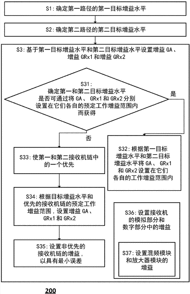
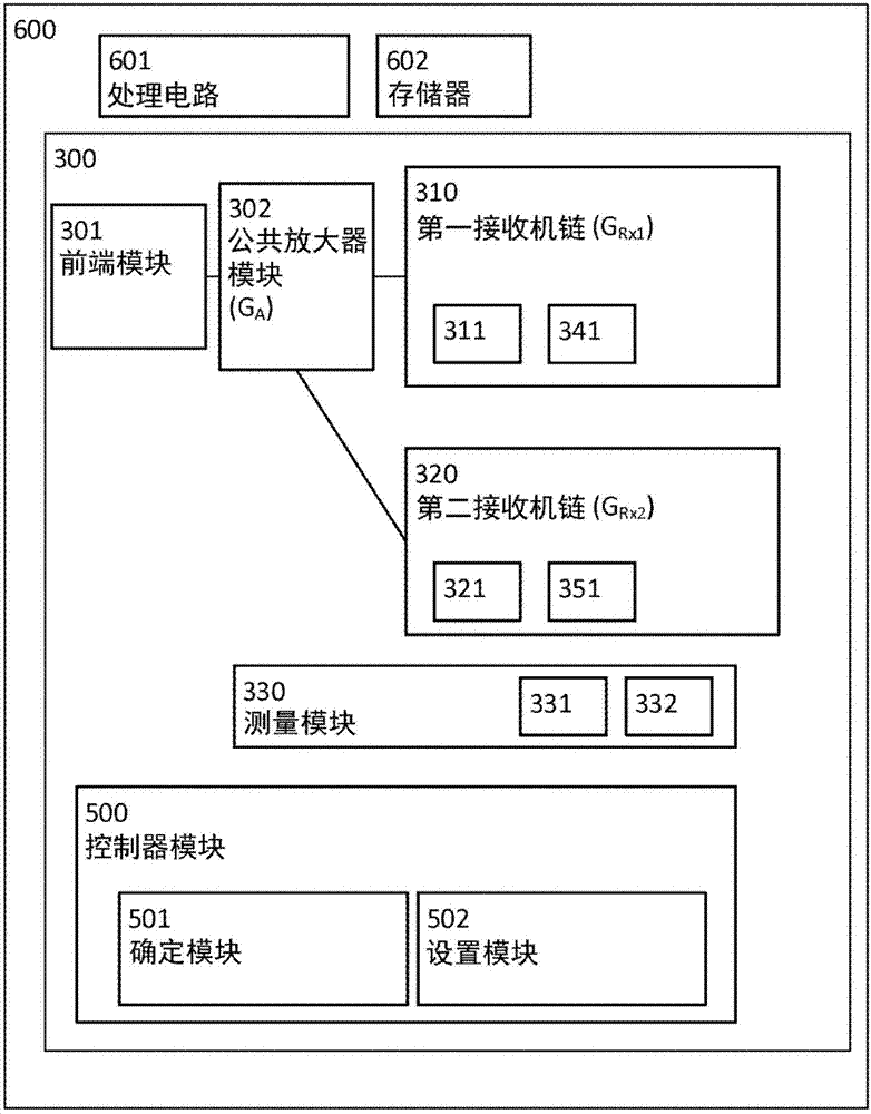
This disclosure provides a method for gain control in a wireless receiver. The wireless receiver comprises a first receiver chain adapted to receive a first signal in a first frequency range, a second receiver chain adapted to receive a second signal in a second frequency range, and a common amplifier module operatively connected to the first receiver chain and the second receiver chain. The method comprises determining a first target gain level for a first path comprising the common amplifier module and the first receiver chain, and determining a second target gain level for a second path comprising the common amplifier module and the second receiver chain. The method comprises setting a gain GA of the common amplifier module and a gain GRx1 in the first receiver chain and a gain GRx2 in the second receiver chain based on the first target gain level and the second target gain level.

Description

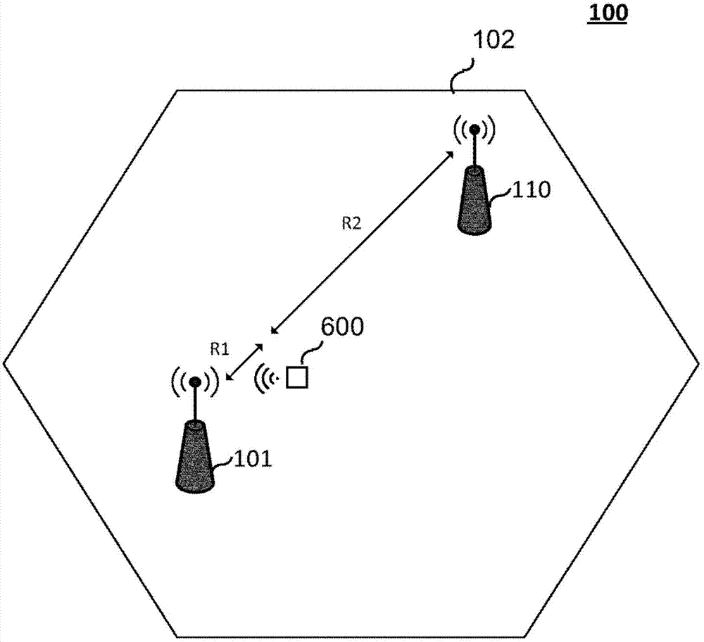
technical field [0001] The present disclosure relates to the field of wireless communications. More particularly, the present disclosure relates to methods of gain control in wireless receivers, related wireless receivers and devices. Background technique [0002] Such as figure 1 A user equipment UE 600 in the shown wireless communication system may receive signals from multiple base stations, for example, a signal from a base station BS 101 and a signal from a base station 110 . The signal from BS 101 and the signal from BS 110 are transmitted using different frequency ranges, for example in the case of 3rd Generation Partnership Project (3GPP) Long Term Evolution (LTE)-Advanced utilizing Carrier Aggregation (CA) or Dual Connectivity. [0003] BSs may not be co-located, especially when operating in non-continuous (NC) CA mode, and UE 600 may experience a different received signal power of the signal from BS 101 than the signal from BS 110 due to transmission loss receiv...

Claims


Application Information

Patent Timeline
Patent Type & Authority Applications(China)
IPC IPC(8): H03G3/30
CPCH03G3/3068H03G3/3078H03G3/008H03G3/3089
Inventor 尼古拉·卡亚金皮特·雅格布森维多利亚·斯拉温斯卡娅
Owner TELEFON AB LM ERICSSON (PUBL)
Why Eureka
Try Eureka