
A new type of durable hot-extruded polyethylene steel wire rope straddle sling

A steel wire rope and steel wire rope technology, applied in the field of bridge engineering, can solve the problems of aggravating the corrosion of the wire rope sling, affecting the service life of the sling, and being unable to effectively resist the dynamic and static load and deformation of the wire rope sling, so as to save painting and maintenance cost, good anti-ultraviolet aging performance, and good environmental stress cracking resistance

Active Publication Date: 2019-03-19
JIANGSU FASTEN STEEL CABLE CO LTD
View PDF8 Cites 0 Cited by
  • Summary
  • Abstract
  • Description
  • Claims
  • Application Information

AI Technical Summary

Problems solved by technology

At present, domestic straddle-type steel wire rope slings use multiple layers of paint for anti-corrosion coating. Using paint for anti-corrosion coating not only requires regular repair and maintenance of the anti-corrosion coating on the surface, but also the anti-corrosion coating on the surface cannot be effective. The coating structure is damaged by external force, so that the outside rainwater and moisture continuously penetrate into the inside of the wire rope body, which intensifies the corrosion of the wire rope sling and affects the service life of the sling.

Method used


Image

  • A new type of durable hot-extruded polyethylene steel wire rope straddle sling
  • A new type of durable hot-extruded polyethylene steel wire rope straddle sling
  • A new type of durable hot-extruded polyethylene steel wire rope straddle sling

Examples


Embodiment Construction

[0041] The present invention will be further described in detail below in conjunction with the accompanying drawings and embodiments.

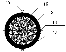
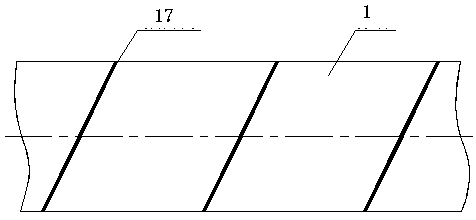
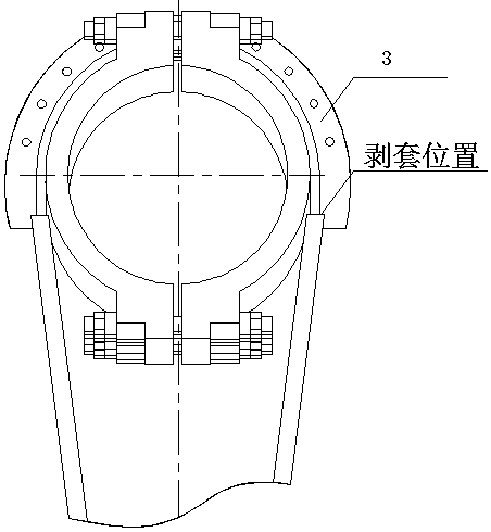
[0042] The novel durable heat-extruded polyethylene steel wire rope straddle type sling structure in this embodiment includes a wire rope sling 1, a cable clamp 2, a protective cover 3, a wire rope sling clamp, a steel wire rope shock absorber, and a wire rope anchor head, the multi-strand steel wire rope sling rides on the cable clamp 2, the steel wire rope sling clamp is arranged on the steel wire rope sling below the cable clamp, and the steel wire rope sling shock mount is arranged on the steel wire rope sling below the steel wire rope clamp; The outer periphery of clip 2 is formed with an embedded cable groove, and the wire rope sling rides in the embedded cable groove of the cable clip, and the steel wire rope sling is stripped at the position in contact with the cable clip to form a bare steel wire section. Filled with butyl rubber mate...


PUM

PropertyMeasurementUnit
heightaaaaaaaaaa

Abstract

The invention relates to a novel durable hot-extrusion polyethylene steel wire rope straddle-type suspension cable structure which comprises steel wire rope suspension cables, a cable clamp, protective covers and steel wire rope suspension cable clamps. The multi-strand steel wire rope suspension cables are straddled on the cable clamp; the steel wire rope suspension cable clamps are arranged on the positions, below the cable clamp, of the steel wire rope suspension cables; a steel wire rope suspension cable damping frame is arranged on the positions, below the steel wire rope suspension cable clamps, of the steel wire rope suspension cables; cable embedding grooves are formed in the periphery of the cable clamp; and the steel wire rope suspension cables are straddled in the cable embedding grooves of the cable clamp. The positions, making contact with the cable clamp, of the steel wire rope suspension cables are subjected to sleeve peeling to form exposed steel wire sections, the sleeve peeling transition part is filled with sealing rubber materials, the protective covers are arranged outside the cable embedding grooves correspondingly, the arc length of each protective cover is larger than the sleeve peeling length of each steel wire rope, and it is guaranteed that exposed steel wires are all arranged inside the protective covers in a covered mode. Outside rainwater and water vapor are effectively prevented from entering the suspension cable steel wire ropes, and the later maintenance cost of the steel wire rope suspension cables is saved.

Description

technical field [0001] The invention relates to a novel durable steel wire rope straddle-type sling structure, which is mainly used for suspension bridge slings and belongs to the technical field of bridge engineering. Background technique [0002] Suspension bridge sling is a force-transmitting member that transmits the self-weight and external load of the stiffening beam to the main cable, and is the link connecting the stiffening beam and the main cable. According to the different connection methods between the sling and the clamp, it can be divided into a straddle sling and a pinned sling. The straddle sling generally adopts a steel wire rope sling, and the steel wire rope with anchor heads at both ends rides in the embedded cable groove on the top of the cable clamp, and the anchor head is connected with the stiffening beam. The outside of the sling wire rope is painted with paint for anti-corrosion. The sling has been subjected to fatigue loads for a long time, and i...

Claims


Application Information

Patent Timeline
Patent Type & Authority Patents(China)
IPC IPC(8): E01D19/16B29C48/15
CPCB29C48/15E01D19/16
Inventor 赵军薛花娟卢靖宇周祝兵吴琼翟鹏程
Owner JIANGSU FASTEN STEEL CABLE CO LTD
Learn More