Continuous casting device
A continuous casting and traction device technology, applied in the field of casting, can solve the problems of poor surface quality, large space occupation, and poor safety of casting slabs, and achieve the effect of improving continuous casting efficiency and reducing the overall occupied space
- Summary
- Abstract
- Description
- Claims
- Application Information
AI Technical Summary
Problems solved by technology
Method used
Image

Examples
Embodiment 1
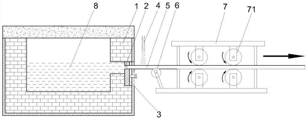
[0038] This embodiment provides a continuous casting device, such as figure 1 shown, including:
[0039] The molten pool 1 is used to store molten metal 8 and has through holes 2 for continuous casting;
[0040] The lead rod 5 can sealably extend into the continuous casting through hole 2, and is used to guide the metal that has solidified in the continuous casting through hole 2 from the continuous casting through hole 2 to the molten pool 1 when the continuous casting starts. external operation;
[0041] The cooling device 4 is used for cooling the lead rod 5 or the solidified metal, and through the heat transfer effect of the lead rod or the solidified metal, the molten metal located in the continuous casting through hole 2 flows in the lead rod 5 Or further cooling and solidification on already solidified metal;
[0042] The pulling device 7 is used to pull the draw bar 5 or the solidified metal away from the molten pool 1 .
[0043]In the continuous casting device of ...
Embodiment 2
[0071] The present embodiment provides a continuous casting method, comprising the following steps:
[0072] S1: plugging the continuous casting through hole 2 located on the side wall of the molten pool 1 with a refractory material;
[0073] S2: Inject molten metal into the molten pool 1 to make the molten metal higher than the continuous casting through hole 2;
[0074] S3: Place the guide rod 5 on the traction device 7, and use the guide rod 5 to open the refractory material in the continuous casting through hole 2 after aligning with the continuous casting through hole 2, so that the guide rod 5 enters the continuous casting through hole 2;
[0075] S4: Open the cooling device 4 to cool the lead rod 5, so that the molten metal positioned in the continuous casting through hole 2 is cooled and solidified at the front end of the lead rod 5 (only at the beginning of continuous casting, the molten metal is cooled at the front end of the lead rod 5 solidification, and then the ...
Embodiment 3
[0084] This embodiment specifically provides a continuous casting method for aluminum alloy liquid, comprising the following steps:
[0085] S1: plugging the continuous casting through hole 2 located on the side wall of the molten pool 1 with a refractory material;
[0086] S2: Inject aluminum alloy liquid into the molten pool 1 so that the aluminum alloy liquid is 10mm higher than the horizontal centerline of the continuous casting through hole 2, and in the subsequent steps, the aluminum alloy liquid in the molten pool 1 should maintain this distance so that The temperature of the aluminum alloy liquid in molten pool 1 is maintained at 670°C;
[0087] S3: Place the guide rod 5 on the traction device 7, and use the guide rod 5 to open the refractory material in the continuous casting through hole 2 after aligning with the continuous casting through hole 2, so that the guide rod 5 enters the continuous casting through hole 2;
[0088] S4: Open the cooling device 4 to cool the...
PUM
| Property | Measurement | Unit |
|---|---|---|
| diameter | aaaaa | aaaaa |
| thickness | aaaaa | aaaaa |
| diameter | aaaaa | aaaaa |
Abstract
Description
Claims
Application Information
 - R&D
- Intellectual Property
- Life Sciences
- Materials
- Tech Scout
- Unparalleled Data Quality
- Higher Quality Content
- 60% Fewer Hallucinations
Browse by: Latest US Patents, China's latest patents, Technical Efficacy Thesaurus, Application Domain, Technology Topic, Popular Technical Reports.
© 2025 PatSnap. All rights reserved.Legal|Privacy policy|Modern Slavery Act Transparency Statement|Sitemap|About US| Contact US: help@patsnap.com