
T-type dual-cantilever beam-type single-pole double-throw switch

A single-pole double-throw switch, double cantilever beam technology, applied in the field of radio frequency MEMS, can solve the problems of reducing switch life, increasing the complexity of radio frequency MEMS switches, etc., to increase isolation, enhance switch life and microwave performance, enhance The effect of effective contact

Inactive Publication Date: 2017-11-24
ZHONGBEI UNIV
View PDF10 Cites 6 Cited by
  • Summary
  • Abstract
  • Description
  • Claims
  • Application Information

AI Technical Summary

Problems solved by technology

For example, the Institute of Microelectronics, Chinese Academy of Sciences has designed a new type of electromagnetically driven push-pull RF MEMS switch, which adopts a stress-free monocrystalline silicon torsion beam structure. When the switch coil has no external current, the switches A and B are in the off state, and the coil When a forward current is applied, a pulling force is applied to end A of the beam, and a push force is applied to end B of the beam. The switch A is in the open state and B is in the off state. When the reverse current is applied to the coil, opposite forces are generated at both ends of A and B. At this time , A is in the off state, and B is in the on state. When the RF MEMS switch is working, the entire device needs to be placed in a uniform magnetic field, and the magnetic field lines pass through the Au coil vertically, thus increasing the complexity of the RF MEMS switch. Another example The 55th Institute of China Electronics Co., Ltd. discloses a radio frequency MEMS switch containing a shark-tooth contact system (application number: CN201010584317.6). The shark-tooth contact system includes two sets of high and low contacts, each set of contacts includes Contacts with a consistent height, but it is difficult to achieve the same height during production, so that there will be a virtual connection in the two contacts of the same group, which reduces the life of the switch

Method used


Image

  • T-type dual-cantilever beam-type single-pole double-throw switch
  • T-type dual-cantilever beam-type single-pole double-throw switch
  • T-type dual-cantilever beam-type single-pole double-throw switch

Examples


Embodiment Construction

[0041] Embodiments of the present invention are described in detail below, examples of which are shown in the drawings, wherein the same or similar reference numerals designate the same or similar elements or elements having the same or similar functions throughout. The embodiments described below by referring to the figures are exemplary only for explaining the present invention and should not be construed as limiting the present invention.

[0042] In the description of the present invention, it should be understood that the orientations or positional relationships indicated by the terms "center", "upper", "lower", "front", "rear", "left", "right" etc. are based on the attached The orientation or positional relationship shown in the figure is only for the convenience of describing the present invention and simplifying the description, and does not indicate or imply that the referred combination or element must have a specific orientation, be constructed and operated in a spec...


PUM


Abstract

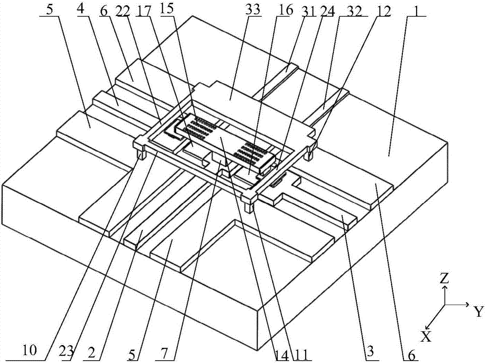
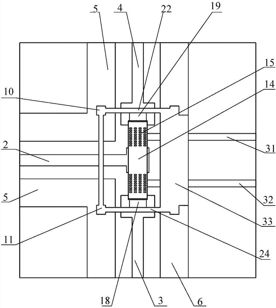
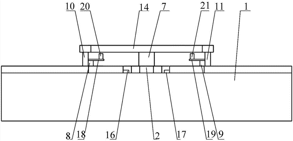
A T-type dual-cantilever beam-type single-pole double-throw switch is mainly formed by a structure, a microwave transmission line, a driving electrode, an upper electrode, a lower electrode, a mooring anchor and an air bridge. The microwave transmission line and the driving electrode are arranged on the substrate, the upper electrode is a dual-cantilever beam, a middle anchor supports two cantilever beam structures respectively arranged at left and right sides, and the lower electrode employs a single contact, double contacts and three contacts which have elastic beams. At the aspect of mechanical aspects, the impact force for the lower electrode can be reduced caused by rapidly pulling the upper electrode due to the electrostatic force effect to play a buffer effect so as to protect the contacts and the upper electrode so as to enhance the effective contact and avoid ablation and adhesion caused by weak contact. When driving voltage is applied on a first driving electrode, the upper electrode is pulled down under the effect of the electrostatic force and then is contacted with the contacts, the switch is located in a conduction state, the upper electrode at the upper portion of a second driving electrode is warped so as to increase the isolation of the switch, avoid the self actuation between the upper electrode and the lower electrode and enhance the switch life and the microwave performance.

Description

technical field [0001] The invention belongs to the technical field of radio frequency MEMS, and in particular relates to a T-shaped double cantilever beam type single-pole double-throw switch. Background technique [0002] RF MEMS switch is a research hotspot in the field of MEMS since the 1990s. RF MEMS single-pole single-throw switch is a basic device of microwave circuits. Its function is to control the on-off of microwave signals in the transmission system. It is mainly used in microwave signal sources In pulse modulators, attenuators, phase shifters, T / R components. [0003] At present, the institutions that conduct research on RF MEMS switches mainly include the 13th Institute of China Power Group, the 55th Institute of China Power Group, the Institute of Microelectronics of Tsinghua University, Southeast University, the Institute of Electronics of the Chinese Academy of Sciences, and North University of China. For example, the Institute of Microelectronics, Chinese ...

Claims


Application Information

Patent Timeline
Patent Type & Authority Applications(China)
IPC IPC(8): H01H59/00
CPCH01H59/0009
Inventor 李孟委王楠张一飞刘秋慧高跃升吴倩楠王莉
Owner ZHONGBEI UNIV
Learn More