Piezoelectric-driven two-degrees-of-freedom decoupling slight swing platform

A piezoelectric drive, degree of freedom technology, applied in the field of micro-positioning, can solve the problems of high assembly precision, influence of platform motion precision, increase of platform processing cost, etc., to reduce control difficulty, improve static and dynamic characteristics, and compact structure Effect

Active Publication Date: 2017-11-24
TIANJIN UNIV
View PDF11 Cites 10 Cited by
  • Summary
  • Abstract
  • Description
  • Claims
  • Application Information

AI Technical Summary

Problems solved by technology

At present, some scholars have designed a variety of micro-swing platforms that can realize two-degree-of-freedom swings, but these micro-swing platforms are mostly multi-degree-of-freedom platforms (the number of degrees of freedom is greater than 2), and their X-axis and Y-axis swing motions are coupled. Precise X-axis and Y-axis swings can only be achieved due to kinematic decoupling, which increases the difficulty of control
In addition, most of these platforms are assembled through assembly, and the motion accuracy of the platform is affected by the assembly accuracy, and the motion accuracy of the platform is not high; in addition, due to the high requirements for assembly accuracy, the processing cost of the platform is increased.

Method used


Image

  • Piezoelectric-driven two-degrees-of-freedom decoupling slight swing platform
  • Piezoelectric-driven two-degrees-of-freedom decoupling slight swing platform
  • Piezoelectric-driven two-degrees-of-freedom decoupling slight swing platform

Examples


Embodiment Construction

[0016] In order to further understand the invention content, characteristics and effects of the present invention, the following examples are given, and detailed descriptions are as follows in conjunction with the accompanying drawings:

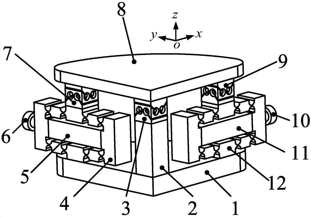
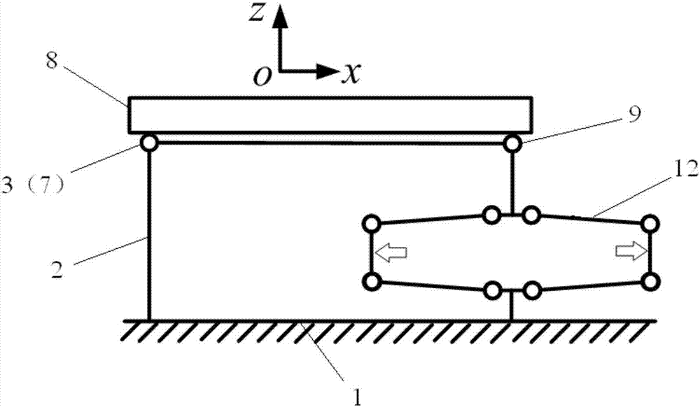
[0017] see Figure 1 ~ Figure 3 , the embodiment of the present invention protects a piezoelectric-driven two-degree-of-freedom decoupling micro-oscillating platform, including a base 1, a column 2, a decoupling Hooke hinge 3, an X-axis bridge-type amplification mechanism 12, and an X-axis piezoelectric ceramic driver 11. X-axis pre-tightening bolt 10, X-axis Hooke hinge 9, Y-axis bridge amplification mechanism 4, Y-axis piezoelectric ceramic driver 5, Y-axis pre-tightening bolt 6, Y-axis Hooke hinge 7, working platform 8.

[0018] In this embodiment, the base 1 is a triangular or fan-shaped flat plate, and the X-axis and Y-axis bridge-type amplification mechanisms 12 and 4 are installed on the outside of the two sides of the triangle or fan-...


PUM


Abstract

The invention discloses a piezoelectric-driven two-degrees-of-freedom decoupling slight swing platform. The piezoelectric-driven two-degrees-of-freedom decoupling slight swing platform comprises a base, a stand column, a decoupling hook hinge, an X-axis bridge type amplification mechanism, an X-axis piezoelectric ceramic driver, an X-axis pre-tightening bolt, an X-axis hook hinge, a Y-axis bridge type amplification mechanism, a Y-axis piezoelectric ceramic driver, a Y-axis pre-tightening bolt, a Y-axis hook hinge and a working platform. The X-axis bridge type amplification mechanism and the Y-axis bridge type amplification mechanism are mounted on the outer sides of the two sides of the base. The vertex distances of the X-axis bridge type amplification mechanism and the Y-axis bridge type amplification mechanism and the base are equal, the X-axis piezoelectric ceramic driver is mounted in the X-axis bridge type amplification mechanism through the X-axis pre-tightening bolt, and the Y-axis piezoelectric ceramic driver is mounted in the Y-axis bridge type amplification mechanism through the Y-axis pre-tightening bolt. Each of the X-axis bridge type amplification mechanism and the Y-axis bridge type amplification mechanism comprises flexible hinge mechanisms symmetrically arranged on the two sides of the X-axis piezoelectric ceramic driver or the Y-axis piezoelectric ceramic driver and a beam for connecting the bridge type flexible hinge mechanisms. The X-axis bridge type amplification mechanism is connected with the working platform through the X-axis hook hinge, and the Y-axis bridge type amplification mechanism is connected with the working platform through the Y-axis hook hinge. By the adoption of the piezoelectric-driven two-degrees-of-freedom decoupling slight swing platform, the two-degrees-of-freedom decoupling precision slight swing can be achieved.

Description

technical field [0001] The invention belongs to the field of micro-positioning, and in particular relates to a two-degree-of-freedom decoupling micro-oscillating platform directly driven by a piezoelectric ceramic driver. Background technique [0002] In recent years, with the development of bioengineering, material science, and microelectronics technology, the objects of micro-nano manipulation are getting smaller and smaller, and the precision of micro-nano manipulation is getting higher and higher. In order to ensure the accuracy of precise micro-nano operations, small angle adjustments are particularly important. As an important part of the precision micro-nano operating system, the two-degree-of-freedom micro-swing platform plays a vital role in the micro-nano operation. The two-degree-of-freedom micro-swing platform can realize the micro-swing of the X-axis and the Y-axis, which is used to adjust the angle of the positioning platform during the micro-nano operation, t...

Claims


Application Information

Patent Timeline
Patent Type & Authority Applications(China)
IPC IPC(8): B23Q1/34
CPCB23Q1/34
Inventor 梁存满王福军田延岭张大卫
Owner TIANJIN UNIV
Why Eureka
Try Eureka