
Guide unit guide roller cooling system

A cooling system and guide roller technology, applied in the field of guide and guard devices, can solve the problems of waste of water resources, accelerated wear of guide rollers, and low degree of automation, so as to save energy, save water resources, and avoid working all the time

Inactive Publication Date: 2017-11-24
HEFEI ORIENT METALLURGICAL EQUIP
View PDF5 Cites 3 Cited by
  • Summary
  • Abstract
  • Description
  • Claims
  • Application Information

AI Technical Summary

Problems solved by technology

[0002] The guide rollers on the existing guides work for a long time, due to contact and friction with the steel rolling, the phenomenon of heat generation of the guide rollers is serious, because the hardness and wear resistance of the metal at high temperatures are reduced, so the guide rollers at high temperatures and the steel rolling Continued contact friction will further accelerate the wear of the guide roller and reduce the service life of the guide roller. In the prior art, the method of spraying cold water on the guide roller is often used to cool it down. For example, patents 2016212308840 and 2016211875641 spray cold water through the guide roller through the pipeline This way of cooling is not highly automated, it cannot detect the real-time temperature of the guide roller, and it is easy to cause waste of water resources. Therefore, it is necessary to invent a cooling system for guide rollers to solve the above problems

Method used


Image

  • Guide unit guide roller cooling system
  • Guide unit guide roller cooling system

Examples


Embodiment Construction

[0018] The following will clearly and completely describe the technical solutions in the embodiments of the present invention with reference to the accompanying drawings in the embodiments of the present invention. Obviously, the described embodiments are only some, not all, embodiments of the present invention. Based on the embodiments of the present invention, all other embodiments obtained by persons of ordinary skill in the art without making creative efforts belong to the protection scope of the present invention.

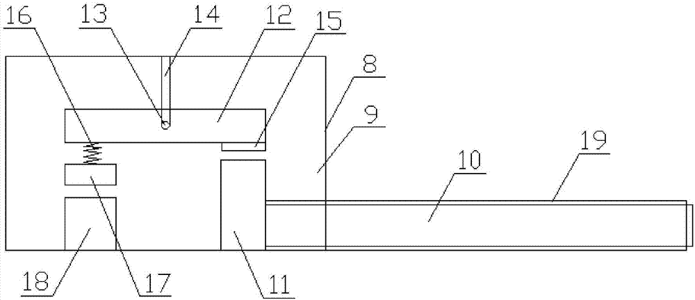
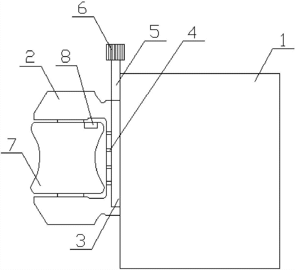
[0019] The present invention provides such Figure 1-2 A guide roller cooling system shown includes a guide 1, one side of the guide 1 is fixed with a guide roller support arm 2, and the top of the guide roller support arm 2 is provided with a cold water pipe 3, and the cold water The pipe 3 is fixedly connected with the guide 1, the cold water pipe 3 is provided with a nozzle 4, one end of the cold water pipe 3 is connected with a water inlet pipe 5, and one ...


PUM


Abstract

The invention discloses a guide unit guide roller cooling system. The guide unit guide roller cooling system comprises a guide unit, a guide roller supporting arm is fixedly arranged on one side of the guide unit, a cold water pipe is arranged at the top of the guide roller supporting arm and is fixedly connected with the guide unit, a spraying head is arranged on the cold water pipe, one end of the cold water pipe is connected with a water inlet pipe, a water pump motor is arranged on one side of the water inlet pipe, a guide roller is arranged on the guide roller supporting arm, and a temperature control device is arranged on the guide roller. According to the guide unit guide roller cooling system, a heat conduction bar and a shape memory alloy are arranged, and therefore the heat conduction bar can better transmit the temperature of the guide roller to the shape memory alloy, and the shape memory alloy is controlled to extend and contract; and a supporting frame, an electrode plate and an electric contact bar are arranged, and therefore the shape memory alloy can better deform to control the supporting frame to ascend and descend, the supporting frame ascends and descends to control contact between the electrode plate and the electric contact bar, starting and stopping of the water pump motor are controlled, constant work of the water pump motor is avoided, energy resources are saved, and the water resource is saved.

Description

technical field [0001] The invention relates to the field of guide devices, in particular to a cooling system for guide rollers. Background technique [0002] The guide rollers on the existing guides work for a long time, due to contact and friction with the steel rolling, the phenomenon of heat generation of the guide rollers is serious, because the hardness and wear resistance of the metal at high temperatures are reduced, so the guide rollers at high temperatures and the steel rolling Continued contact friction will further accelerate the wear of the guide roller and reduce the service life of the guide roller. In the prior art, the method of spraying cold water on the guide roller is often used to cool it down. For example, patents 2016212308840 and 2016211875641 spray cold water through the guide roller through the pipeline This way of cooling is not highly automated, it cannot detect the real-time temperature of the guide rollers, and it is easy to cause waste of water...

Claims


Application Information

Patent Timeline
Patent Type & Authority Applications(China)
IPC IPC(8): B21B39/14G05D23/275
CPCB21B39/14G05D23/275
Inventor 赵家柱张有德梁海峰吴鹏郁应海史宣菊胡峰魏强王磊吴翠凤季方吴迪
Owner HEFEI ORIENT METALLURGICAL EQUIP
Learn More