


Quick Research
Generate reliable direction feasibility study reports for your R&D in just a few steps.

Technical Q&A
Discover and master advanced knowledge NOW. Basics, ideas, possibilities, all at once.

Find Solutions
As an expert in R&D theories, this can generate solutions to your technical problems instantly.

Evaluate Feasibility
Analyze your overall solution with one click, know your potential R&D risks in advance.

Monitor Landscape
Get weekly tech updates, stay abreast of the latest tech innovations and key insights.
A Realization Method of Dynamically Controlled Photonic Crystal Slow Light
A photonic crystal and dynamic control technology, applied in the field of optics, can solve the problems of large group velocity dispersion, narrow slow light bandwidth, refractive index position and group velocity cannot be dynamically changed, etc., to achieve low group velocity, maintain broadband, and stabilize slow light effect of effect
- Summary
- Abstract
- Description
- Claims
- Application Information
AI Technical Summary
Problems solved by technology
Method used
Image

Examples
example 1
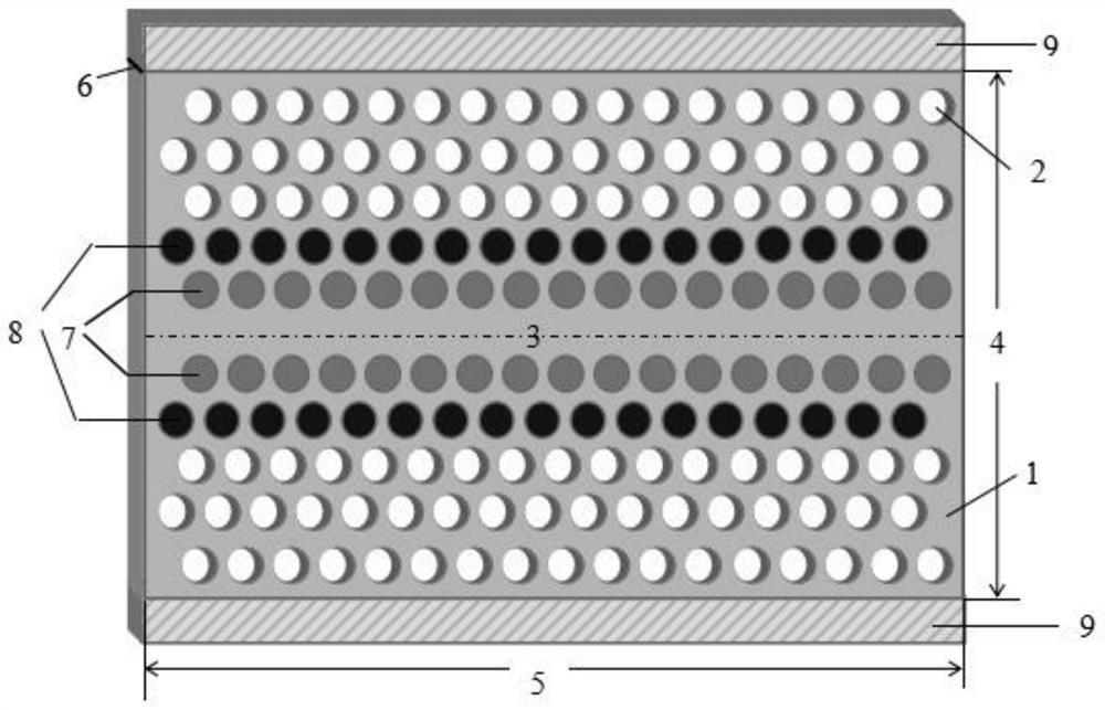
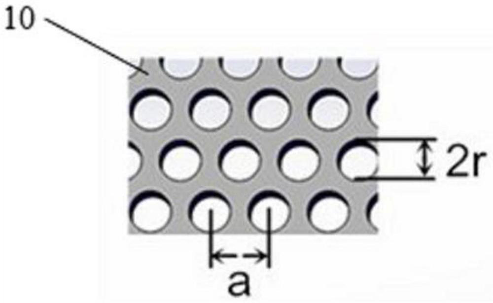
[0038] Construct a low-scattering photonic crystal slow light waveguide device for the purpose of obtaining a higher group refractive index, take the lattice constant a=330nm of the triangular lattice arranged by air holes, and take 0.328a=108.24nm for the air hole radius r, and the waveguide The air holes in the first row on both sides are filled with ordinary organic polymers 1 =1.74, the electro-optic coefficient of hole filling in the second row γ 33 =180pm / V,n poly = 1.6 photoorganic polymer polystyrene, applied voltage 120V, after reaching stability, the refractive index n of the organic polymer polystyrene in the second row of holes 2 Decrease to obtain the average group refractive index of the flat region of the device The flat slow light region appears near the third communication window of the optical fiber at 1530-1536.3nm, with a bandwidth of 6.3nm (group refractive index variation range n g within ±10%), the maximum group velocity dispersion coefficient β in t...
example 2
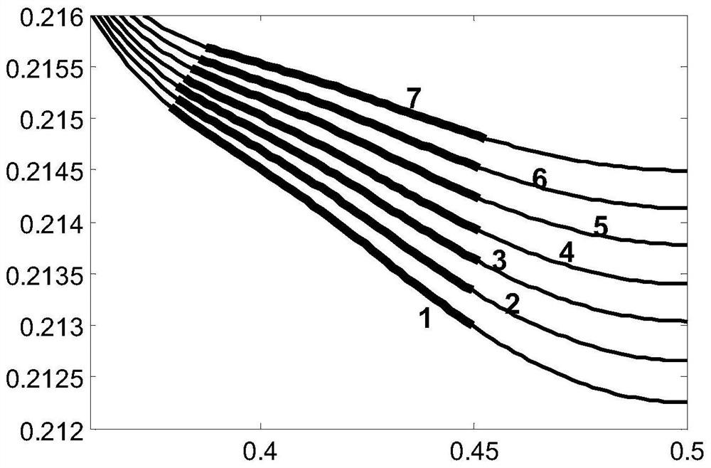
[0040] Construct a low-scattering photonic crystal slow light waveguide device for the purpose of obtaining a wider bandwidth, take the external voltage as 0V, and the second row of organic polymer refractive index n 2 = 1.6, other conditions are the same as Example 1, and the average group refractive index of the flat broadband slow light region of the device is obtained Flat slow light appears in the 15.2nm range from 1534.1nm to 1549.3nm (group refractive index variation range n g Within ±10%, it is regarded as the equilibrium unchanged, such as image 3 , 4 , shown in curve 1 in 5), the maximum group velocity dispersion coefficient β in the flat band 2 2 / mm, the normalized delay-bandwidth product reaches 0.3355, wider bandwidth, lower dispersion, and stronger delay storage capability.
example 3
[0042] Construct a broadband low-dispersion photonic crystal slow light waveguide device in the low-frequency (long-wave) terahertz region, take the lattice constant a of the triangular lattice arranged with air holes = 64 μm, take the radius of the circular air holes as 0.328a = 20.99 μm, the waveguide The air holes in the first row on both sides are filled with ordinary organic polymers 1 =1.74, the electro-optic coefficient of hole filling in the second row γ 33 =180pm / V,n poly = 1.6 electro-optic organic polymer, the two sides of the waveguide are applied with an external voltage of 20V, and after the slow light is stably transmitted, the refractive index of the organic polymer in the second row of holes is reduced to n 2 =1.53, to obtain the average group refractive index in the slow light flat region Flat slow light appears in the 2.6μm range from 297.4μm to 300.0μm (frequency about 1THz) (group refractive index variation range n g within ±10%), the maximum group vel...
PUM
| Property | Measurement | Unit |
|---|---|---|
| refractive index | aaaaa | aaaaa |
Abstract
Description
Claims
Application Information
 - R&D Engineer
- R&D Manager
- IP Professional
- Industry Leading Data Capabilities
- Powerful AI technology
- Patent DNA Extraction
Browse by: Latest US Patents, China's latest patents, Technical Efficacy Thesaurus, Application Domain, Technology Topic, Popular Technical Reports.
© 2024 PatSnap. All rights reserved.Legal|Privacy policy|Modern Slavery Act Transparency Statement|Sitemap|About US| Contact US: help@patsnap.com