A Rehabilitation Robot Revolving Joint Permanent Magnet Assisting Mechanism

A rehabilitation robot and rotary joint technology, applied in passive exercise equipment, physical therapy, etc., can solve the problems of unbalanced power output, low reliability, large axial force, etc., and achieve the effect of balanced power output and compact structure

Active Publication Date: 2019-06-07
HARBIN UNIV OF SCI & TECH
View PDF10 Cites 0 Cited by
  • Summary
  • Abstract
  • Description
  • Claims
  • Application Information

AI Technical Summary

Problems solved by technology

As a clean energy source, magnetic energy has been widely used in machinery, electronics, aerospace, chemical industry, transportation and other fields. At present, magnetic bearings, magnetic gears, magnetic chucks, magnetic couplings, magnetic pumps, magnetic springs, and magnetic energy harvesting have been developed. Devices and other types of magnetic machinery, the basic principle applied by these magnetic machinery is the basic property that the same-sex magnetic poles repel each other and the opposite-sex magnetic poles attract each other. my country has abundant permanent magnet material deposits, and the most widely used magnetic material is rubidium Iron-boron material, NdFeB material per square centimeter can generate 2kg-5kg of repulsion. However, there is no rehabilitation robot rotary joint booster mechanism on the market that utilizes the excellent characteristics of magnetic materials. Most of them use pneumatic drive, hydraulic drive, and Motor-driven, pneumatic-driven power-assisted structures are often accompanied by noise, hydraulic-driven power-assisted mechanisms are often accompanied by leakage, and motor-driven power-assisted structures are often difficult to wear
[0003] In response to the above problems, related patents have also been submitted in China, a magnetic power assist device (patent number CN104038105), which proposes a permanent magnet power assist mechanism, including a rotating shaft, a first permanent magnet, and a second permanent magnet. By changing the distance between permanent magnets and the direction of the magnetic field set by the inclination angle, so that a cutting magnetic field is generated between the permanent magnets, and then a magnetic field force is generated. This scheme is technically effective, but it has some technical defects. The arrangement of the permanent magnets in this device is radial magnetization, The magnetic direction is arranged obliquely. This kind of arrangement direction is easy to generate a large axial force, which affects the reliability of the device. The device changes the direction of the magnetic field by changing the inclination angle between the permanent magnets, which requires high installation accuracy, and the output power of the device The size cannot be adjusted, and the application range is small
[0004] Magnetic booster (Patent No. CN201393190Y) proposes a permanent magnet booster, including a housing, a rotor, a magnetic resistance coil, a magnetic steel, a lever, and a tension spring. There is an opening corresponding to the magnetic steel of the ring, and the periodic opening of the opening relative to the magnetic steel can realize the periodic assisting effect on the rotor. This scheme is technically effective, but it has some technical defects. , firstly, the device can only provide power assistance when the opening of the magnetic resistance coil is opposite to the position of the magnetic steel, the power output during the power assistance period is unbalanced, and the effective power assistance time is short. The protrusion on the ring realizes the periodical opening of the through opening relative to the magnetic steel, and then realizes the periodic assisting movement. The extension spring will deform during use, and it is difficult to ensure that the opening of the magnetic resistance ring can be opened accurately and periodically after repeated use. It greatly affects the boosting effect, and the reliability is low. Again, the output boosting power of the device cannot be adjusted, and the application range is small
[0005] The permanent magnet booster (patent number CN2493778Y) proposes a permanent magnet booster mechanism, including a main shaft, a runner, a booster arm, a large gear, and a pinion. When working, an external force is applied to the pinion to drive the main shaft and the The runners rotate at the same time, and the runners meet the magnets of the same polarity on the booster arm to generate repulsive force, and the repulsive force is converted into output power through the main shaft. This scheme is technically effective, but it has some technical defects. The magnetic poles are arranged obliquely opposite to each other. When the magnetic poles of the same name are close to each other, a repulsive force will be generated to hinder the movement of the mechanism, which will affect the normal output of the mechanism and reduce the boosting effect. Moreover, the output boosting value of the device cannot be adjusted, so the application range is small.

Method used


Image

  • A Rehabilitation Robot Revolving Joint Permanent Magnet Assisting Mechanism
  • A Rehabilitation Robot Revolving Joint Permanent Magnet Assisting Mechanism
  • A Rehabilitation Robot Revolving Joint Permanent Magnet Assisting Mechanism

Examples


Embodiment Construction

[0031] In order to make the purpose, technical solutions and advantages of the patent of the present invention clearer, the patent of the present invention is described below through the specific embodiments shown in the accompanying drawings, but it should be understood that these descriptions are only exemplary and not intended to limit the present invention In addition, in the following description, descriptions of known structures and techniques are omitted to avoid unnecessarily confusing the concept of the patent of the present invention.

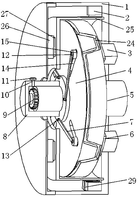
[0032]As shown in the figure, this specific embodiment adopts the following technical solutions: a rehabilitation robot rotary joint permanent magnet booster mechanism, which includes a housing 1, a stator permanent magnet 2, a rotor permanent magnet 3, a turntable base 4, a central shaft 5, and a permanent magnet Bracket 6, pull rod 7, adjustment knob 8, ratchet 9, locking pin holder 10, locking pin unit 11, slider connecting column 1...


PUM


Abstract

The invention discloses a rehabilitation robot rotary joint permanent magnet assisting mechanism, and relates to the field of medical care. The rehabilitation robot rotary joint permanent magnet assisting mechanism comprises a stator unit, a rotor unit, an adjusting unit, a locking unit, a magnetic shielding ring and a central shaft. The stator unit comprises and stator permanent magnets; the rotor unit comprises a rotating substrate, a permanent magnet holding grooves and rotor permanent magnets; the adjusting unit comprises turn button binding posts, slide block units, pull bars and an adjusting turn button; and the locking unit comprises a locking pin unit and a locking pin mounting base. Four groups of permanent magnets are uniformly arranged on the stator mechanism, each group includes two permanent magnets, and like poles of the two permanent magnets are opposite to each other; the permanent magnets are uniformly arranged on the rotor mechanism, the group number of the permanent magnets is the same as that of the stator permanent magnets, and the N poles and the S poles are alternately arranged; when the stator mechanism rotates at an angle, because like magnetic poles mutually repel, opposite magnetic poles attract each other, a generated tangential force drives the rotor to rotate. By changing the size of the air gap between the stator permanent magnets and the rotor permanent magnets, furthermore the magnitude of the output assisting force is changed, and the rehabilitation robot rotary joint permanent magnet assisting mechanism can meet demands of patients of different phases on the rehabilitation assisting power.

Description

technical field [0001] The invention relates to a permanent magnet booster mechanism for a rotary joint of a rehabilitation robot, which belongs to the field of medical care. Background technique [0002] With the improvement of our country's scientific and technological level and people's material living standards, the research of rehabilitation robots has been paid more and more attention by people, and the research of rehabilitation robot assisting mechanism is an important part of the research of rehabilitation robots. As a clean energy source, magnetic energy has been widely used in machinery, electronics, aerospace, chemical industry, transportation and other fields. At present, magnetic bearings, magnetic gears, magnetic chucks, magnetic couplings, magnetic pumps, magnetic springs, and magnetic energy harvesting have been developed. Devices and other types of magnetic machinery, the basic principle applied by these magnetic machinery is the basic property that the same...

Claims


Application Information

Patent Timeline
Patent Type & Authority Patents(China)
IPC IPC(8): A61H1/02
CPCA61H1/02A61H2201/1207A61H2201/14
Inventor 姜金刚马雪峰霍彪张永德韩英帅
Owner HARBIN UNIV OF SCI & TECH
Why Eureka
Try Eureka