Pipe forming die

A technology for forming molds and pipe fittings, applied in the field of pipe bending, which can solve the problems of complex mold structure, troublesome operation, and breakage of pipe bending equipment, and achieve the effects of eliminating cracks or even breakage, fast bending efficiency, and simple structure

Inactive Publication Date: 2017-11-10
芜湖通全科技有限公司
View PDF7 Cites 0 Cited by
  • Summary
  • Abstract
  • Description
  • Claims
  • Application Information

AI Technical Summary

Problems solved by technology

[0003] However, the current pipe bending equipment or mold structure is complicated, the operation is troublesome, and the pipe will be cracked or broken during operation, so that it cannot be used effectively

Method used


Image

  • Pipe forming die
  • Pipe forming die

Examples


Embodiment

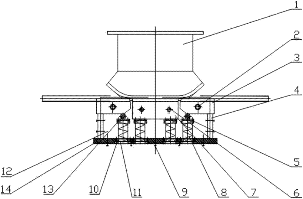
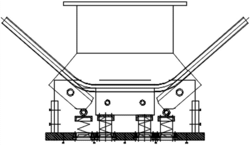
[0025] like figure 2 As shown, the steel pipe is placed between the upper mold 1 and the lower mold 7, and then the movable lower mold 3 is rotated through the pin 2, and the steel pipe is bent along both sides of the upper mold 1.


PUM


Abstract

The invention discloses a pipe fitting forming die, comprising an upper die and a lower die, and is characterized in that: the upper die is provided with a lower die, two sides of the lower die are provided with movable lower dies, and a guide shaft is arranged on the lower die , the movable lower die is provided with a pin shaft, the lower die and the movable lower die are provided with a lower die plate, a spring is arranged between the lower die and the lower die plate, and a spring is arranged between the movable lower die and the lower die plate and the clamping plate, the clamping plate is provided with a guide plate, and a roller is arranged between the spring and the movable lower die; the present invention has a simple structure, and the bending efficiency is fast after the steel pipe enters and is completed, and the problem of cracking or even breaking of the steel pipe is prevented; The present invention is convenient and safe to use, will not accidentally injure staff, is safe and reliable, and can realize multi-angle bending.

Description

technical field [0001] The invention relates to the technical field of pipe bends, in particular to a pipe fitting forming die. Background technique [0002] Bending technology is widely used in boiler and pressure vessel industries, central air-conditioning manufacturing, automobile industry, aerospace industry, shipbuilding and other industries. The quality of bending pipes will directly affect the rational structure of products in these industries performance, safety, reliability, etc. Therefore, in order to bend high-quality pipe fittings, it is necessary to master the processing skills of pipe fittings under different process conditions. For cold bent pipes, it is necessary to reasonably select the formation of the mandrel and master its correct use method. [0003] However, the current pipe bending equipment or molds are complex in structure and cumbersome to operate, and the pipes will be cracked or broken during the operation, so that they cannot be used effectivel...

Claims


Application Information

Patent Timeline
Patent Type & Authority Applications(China)
IPC IPC(8): B21D9/05B21D9/16B21D37/10
CPCB21D9/05B21D9/16B21D37/10
Inventor 季一全汤佳
Owner 芜湖通全科技有限公司
Why Eureka
Try Eureka