


Quick Research
Generate reliable direction feasibility study reports for your R&D in just a few steps.

Technical Q&A
Discover and master advanced knowledge NOW. Basics, ideas, possibilities, all at once.

Find Solutions
As an expert in R&D theories, this can generate solutions to your technical problems instantly.

Evaluate Feasibility
Analyze your overall solution with one click, know your potential R&D risks in advance.

Monitor Landscape
Get weekly tech updates, stay abreast of the latest tech innovations and key insights.
Magnetic levitation guide rail and its air gap thickness control method
A guide rail and maglev technology, applied in the direction of bearings, shafts and bearings, mechanical equipment, etc., can solve the problem of inability to guarantee, and achieve the effect of increasing the use stroke and improving the magnetic levitation air gap.
- Summary
- Abstract
- Description
- Claims
- Application Information
AI Technical Summary
Problems solved by technology
Method used
Image

Examples
Embodiment 1
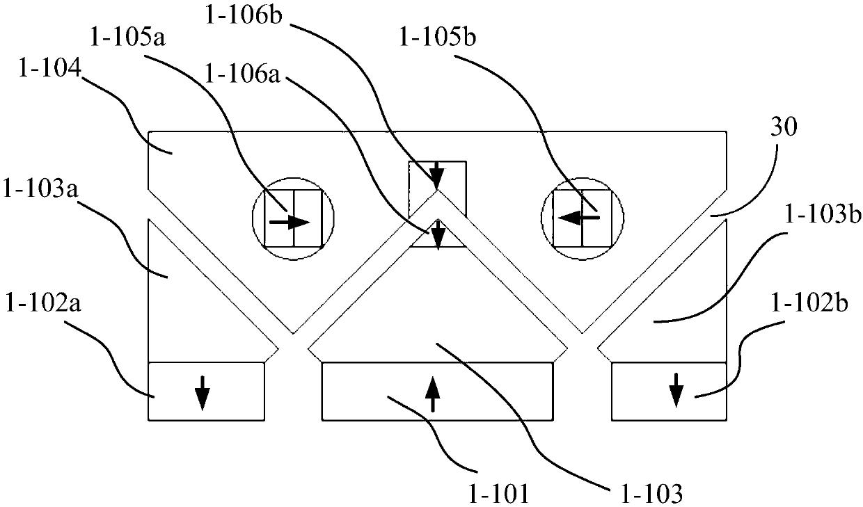
[0031] like image 3 as shown, image 3 Yes figure 2 The cross-sectional side view of the magnetic levitation guide shown in this embodiment, in this embodiment, it can not only provide a stable large-size magnetic levitation working air gap to meet the needs of a frictionless guide rail with a larger stroke, but also can be adjusted arbitrarily like an air flotation system The base air gap thickness even turns off the magnetic levitation function.
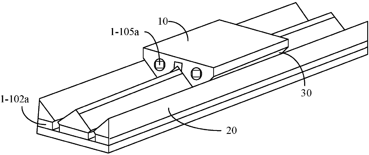
[0032] In this structure, the stator 20 has a plurality of sliding grooves, and the mover 10 floats and slides in the sliding grooves, and the sliding grooves are formed by steel guide rails 1-103, 1-103a, 1-103b. Therefore, it can be understood that when the mover 10 floats on the surface of the stator 20 , the mover 10 has a plurality of tooth-shaped structures protruding into the sliding slots to match the surface shape of the stator 20 . In this embodiment, the mover 10 is the slider frame 1-104. The stator 20 also includ...
Embodiment 2
[0042] like Figure 8 As shown, in this embodiment, 3-101 is an oblique magnetized magnet installed on both sides of the V-shaped groove-shaped guide rail, and its function is similar to that of magnetized magnets 1-101 and 1-102a in Embodiment 1, 1-102b; 3-105 is the rotatable magnet embedded in the slide block, its effect is similar to the rotatable magnet 1-105a, 1-105b in embodiment one; 3-106a, 3-106b is the horizontal stiffness magnet, its effect Similar to the horizontal stiffness magnets 1-106a, 1-106b in Example 1; 3-109a, 3-109b are RX-direction stiffness magnets, which make the RX direction have stiffness, so that the slider cannot be arbitrarily deflected or moved along the X-direction. Can only deflect in a small range.
[0043] In this embodiment, the magnetized magnetic steel is magnetized obliquely compared with the first embodiment, and the horizontal stiffness magnet is located at the bottom of the sliding groove. It can be seen that the present invention d...
PUM
 Abstract
Description
Claims
Application Information
 - R&D Engineer
- R&D Manager
- IP Professional
- Industry Leading Data Capabilities
- Powerful AI technology
- Patent DNA Extraction
Browse by: Latest US Patents, China's latest patents, Technical Efficacy Thesaurus, Application Domain, Technology Topic, Popular Technical Reports.
© 2024 PatSnap. All rights reserved.Legal|Privacy policy|Modern Slavery Act Transparency Statement|Sitemap|About US| Contact US: help@patsnap.com