
Polishing wheel feeding compensation mechanism of polishing machine

A technology of compensation mechanism and polishing wheel, which is applied to the parts of grinding machine tools, grinding/polishing equipment, grinding drive devices, etc., can solve problems such as uncontrollable, harsh environment, and slow speed, so as to improve production efficiency and ensure The effect of processing quality and strengthening stability

Active Publication Date: 2017-11-07
广东埃华路机器人工程有限公司
View PDF5 Cites 1 Cited by
  • Summary
  • Abstract
  • Description
  • Claims
  • Application Information

AI Technical Summary

Problems solved by technology

[0002] In existing polishing machines, as the number of polished workpieces increases, the polishing wheel begins to wear, resulting in inconsistent contact surfaces between the polishing wheel and the workpiece, and even the polishing wheel cannot contact the workpiece, which seriously affects the processing quality of the workpiece
[0003] For this reason, in the traditional polishing machine, the polishing wheel is firmly installed on the dust cover, which cannot be adjusted, and the operator can only rely on the operator to adjust the processing position of the workpiece to the direction of the polishing wheel so that the workpiece is in contact with the polishing wheel
[0004] However, workers grab the workpiece and work on the polishing machine, the speed is relatively slow, the environment is relatively harsh, and there are potential safety hazards; moreover, most operators judge the degree of wear of the polishing wheel based on experience to determine the relative distance between the workpiece and the polishing wheel. Position, resulting in inconsistent polishing effect of the workpiece due to inconsistent operating pressure, reducing the processing quality of the workpiece

Method used


Image

  • Polishing wheel feeding compensation mechanism of polishing machine
  • Polishing wheel feeding compensation mechanism of polishing machine
  • Polishing wheel feeding compensation mechanism of polishing machine

Examples


Embodiment Construction

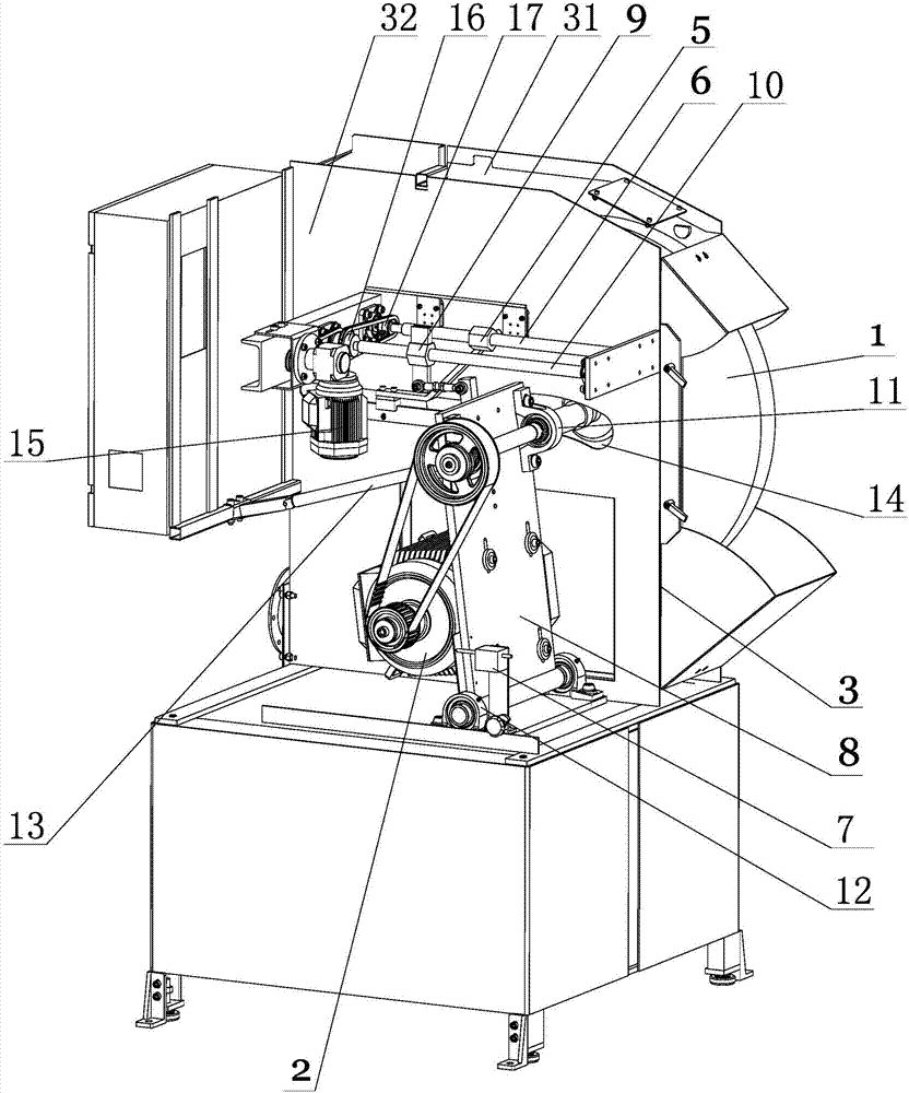
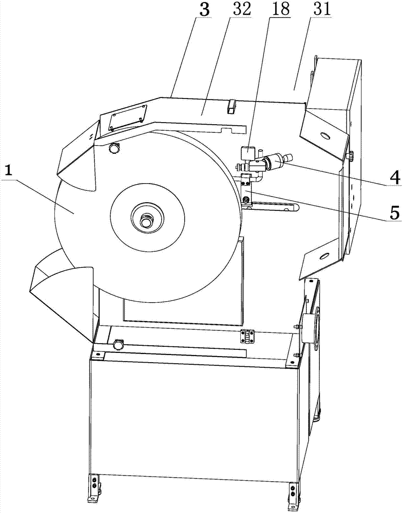
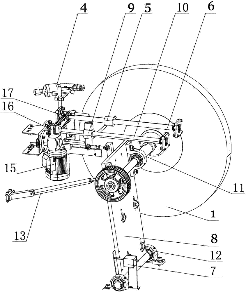
[0020] The present invention will be further described below in conjunction with accompanying drawing, according to Figure 1 to Figure 3 As shown, the polishing wheel feed compensation mechanism of the polishing machine of the present invention includes a polishing wheel 1 , a polishing drive motor 2 and a dust cover 3 . The dust cover 3 is provided with a processing chamber 31 for installing the polishing wheel 1 and a control chamber 32 for installing the polishing drive motor 2. The processing chamber 31 has a processing port for contacting with the workpiece, and the output shaft of the polishing drive motor 2 It is connected with the rotating shaft of the polishing wheel 1 through the output belt. Wherein, the control chamber 32 is provided with a compensation control component for driving the polishing wheel 1 to move forward or backward relative to the processing opening. The compensation control component includes a swing connection assembly and a compensation drive ...


PUM


Abstract

The invention provides a polishing wheel feeding compensation mechanism of a polishing machine. The polishing wheel feeding compensation mechanism comprises a polishing wheel, a polishing driving motor and a dust cover. The dust cover is internally provided with a machining cavity for installing the polishing wheel, and a control cavity for installing the polishing driving motor. The control cavity is provided with a compensation control component, a swinging connection assembly and a compensation driving assembly of the compensation control component are in structural fit with a compensation monitoring component, thus, the position of the polishing wheel can be automatically adjusted according to the change of the polishing pressure in the production process, and a good compensation effect is achieved; and accordingly, the effect that the polishing quality of all workpieces is the same is ensured, manual operation is effectively replaced, the production efficiency is improved, the cost is reduced, and the machining quality is guaranteed.

Description

technical field [0001] The invention relates to a polishing wheel feeding compensation mechanism of a polishing machine. Background technique [0002] In existing polishing machines, as the number of polished workpieces increases, the polishing wheel begins to wear, resulting in inconsistent contact surfaces between the polishing wheel and the workpiece, and even the polishing wheel cannot contact the workpiece, which seriously affects the processing quality of the workpiece. [0003] For this reason, in traditional polishing machines, the polishing wheel is firmly installed on the dust cover, which cannot be regulated, and the operator can only rely on the operator to adjust the position of the workpiece to the direction of the polishing wheel so that the workpiece is in contact with the polishing wheel. [0004] However, workers grab the workpiece and work on the polishing machine, the speed is relatively slow, the environment is relatively harsh, and there are potential s...

Claims


Application Information

Patent Timeline
Patent Type & Authority Applications(China)
IPC IPC(8): B24B47/20
CPCB24B47/20Y02P70/10
Inventor 陈学能叶俊超陆少平邵其昌
Owner 广东埃华路机器人工程有限公司
Learn More