Rotor assembly of centrifugal machine

A centrifuge and rotor technology, applied in centrifuges and other directions, can solve the problems of poor corrosion resistance, poor mechanical strength performance, and prone to noise, etc., achieve reasonable product structure design, improve mechanical strength performance and corrosion resistance performance Effect

Inactive Publication Date: 2017-11-07
合肥明英富海生物科技有限公司
View PDF8 Cites 0 Cited by
  • Summary
  • Abstract
  • Description
  • Claims
  • Application Information

AI Technical Summary

Problems solved by technology

Due to its complex structure, traditional medical centrifuges are prone to noise during use, which affects the surrounding environment
[0003] In addition, the centrifugal components of the existing centrifuges still have defects such as poor corrosion resistance and poor mechanical strength.

Method used


Image

  • Rotor assembly of centrifugal machine
  • Rotor assembly of centrifugal machine

Examples


Embodiment 1

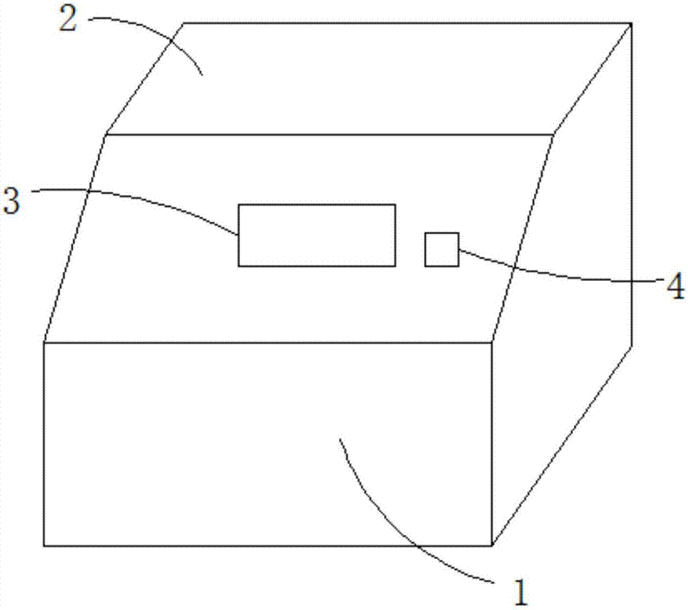
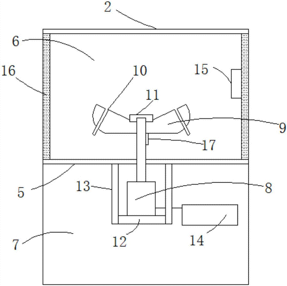
[0028] see figure 1 and figure 2 , the present invention provides a centrifuge, comprising: a housing 1, a cover plate 2 connected to the housing 1, a display screen 3 and a switch 4 arranged on the housing 1, a The centrifugal cavity 6 and the motor cavity 7 inside, the partition plate 5 that separates the centrifugal cavity 6 and the motor cavity 7 in the housing 1, is set in the motor cavity 7 and its drive shaft extends to the centrifugal cavity 6 The drive motor 8 inside, the rotor 9 that is located in the centrifugal cavity 6 and links to each other with the drive shaft of the drive motor 8, a plurality of centrifuge tube jacks 10 that are located on the rotor 9, and that are located in the drive The support frame 12 below the motor 8, the connecting rod 13 connecting the support frame 12 and the partition plate 5, the sound-absorbing material 16 provided on the side wall of the centrifugal chamber 6, and the drive shaft provided at the drive motor 8 The positioning k...

Embodiment 2

[0033] A method for processing a rotor assembly of a centrifuge, the steps are as follows:

[0034] ①, structure and molding

[0035] The rotor assembly includes a rotor connected to the drive motor through a drive shaft. Positioning keys are provided on the peripheral surface of the drive shaft, and fixing bolts are provided at the end of the drive shaft. The rotor is circular, and a connecting hole is provided at the center of the rotor. The drive shaft Through the connection hole, the rotor is fixed on the drive shaft through positioning keys and fixing bolts; the rotor is provided with a plurality of centrifuge tube sockets, and the multiple centrifuge tube sockets are symmetrically distributed about the center of the rotor;

[0036] The rotor is cast by carbon steel, and the centrifuge tube socket and the rotor are integrally formed;

[0037] The material of the drive shaft is Q235 steel, and the processing technology is forging;

[0038] Positioning keys, fixing bolts,...


PUM


Abstract

The invention relates to the technical field of medical facilities, in particular to a rotor assembly of a centrifugal machine. The rotor assembly comprises a drive shaft and a rotor connected with a drive motor. A positioning key is arranged at the circumferential surface of the drive shaft; a fixed bolt is arranged at the end part of the drive shaft; the rotor is in a circular shape; a connecting hole is formed in a circle center part of the rotor; the drive shaft penetrates through the connecting hole; the rotor is fixed onto the drive shaft through the positioning key and the fixed bolt; and a plurality of centrifugal pipe inserting holes are formed in the rotor and are distributed symmetrically relative to the circular center of the rotor. According to the rotor assembly of the centrifugal machine and a processing method thereof, the structure design of the product is reasonable, and especially during a processing process, the drive shaft and the rotor are preprocessed, so that a mechanical strength performance and an anti-corrosion property of the rotor assembly are improved.

Description

technical field [0001] The invention relates to the technical field of medical equipment, in particular to a rotor assembly of a centrifuge. Background technique [0002] A high-speed centrifuge is a device that uses centrifugal force to separate a liquid phase inhomogeneous system. According to the sedimentation coefficient, mass, density, etc. of the substance, it uses a powerful centrifugal force to separate, concentrate and purify the substance. Centrifuges are widely used in biological and medical fields, such as blood separation, virus research, DNA research, drug purification, etc. are widely used in centrifuges. Due to its complex structure, traditional medical centrifuges are prone to noise during use, which affects the surrounding environment. [0003] In addition, the centrifugal assembly of the existing centrifuge also has defects such as poor corrosion resistance and poor mechanical strength. Contents of the invention [0004] The technical problem to be sol...

Claims


Application Information

Patent Timeline
IPC IPC(8): B04B5/12B04B7/00
CPCB04B5/12B04B7/00
Inventor 邬舒群
Owner 合肥明英富海生物科技有限公司
Why Eureka
Try Eureka