Control valves for controlling media, especially fuels

A technology for controlling valves and media, which is applied to fuel injection devices, valve devices, valve details, etc., and can solve problems such as expensive structures, large structural space and complexity of pressure regulating systems.

Active Publication Date: 2021-10-15
ROBERT BOSCH GMBH
View PDF18 Cites 0 Cited by
  • Summary
  • Abstract
  • Description
  • Claims
  • Application Information

AI Technical Summary

Problems solved by technology

This pressure regulation system has proven effective in principle, but has a relatively complex and expensive construction due to the use of two control valves
In addition, a reference pressure chamber is required, so that a relatively large installation space is created for the pressure regulation system

Method used


Image

  • Control valves for controlling media, especially fuels

Examples


Embodiment Construction

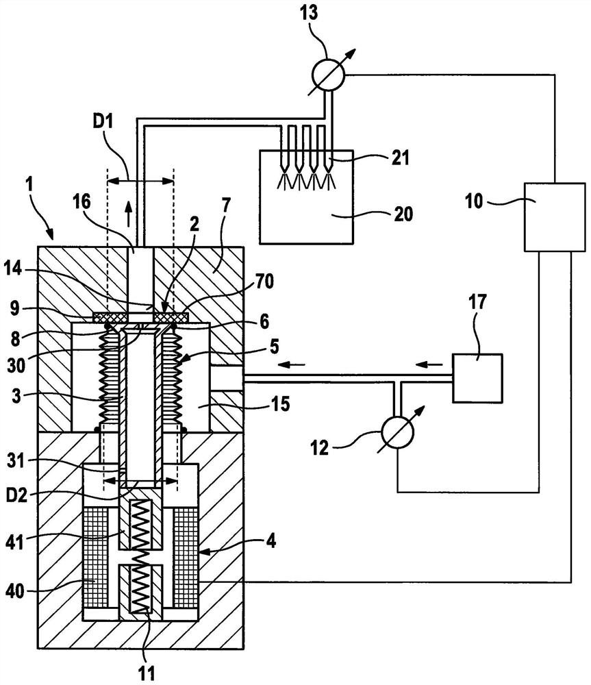
[0018] Refer below figure 1 The control valve 1 for controlling the medium will be described in detail.

[0019] The control valve 1 comprises a sealing seat 2 and a valve element 3 , which in this exemplary embodiment is a valve piston. The valve element 3 has a widened region 8 at the end facing the sealing seat 2 . The widened region 8 widens conically. The valve piston is hollow and has two compensating openings 30 , 31 .

[0020] Furthermore, the control valve 1 comprises an actuator 4 , which in this embodiment is an electromagnetic actuator. The actuator 4 comprises a coil 40 and an armature 41 which is connected to the valve element 3 .

[0021] Furthermore, the valve element 3 is arranged in the bellows 5 . The bellows 5 is fastened to the widened area 8 of the valve element 3 by means of a welded connection. More precisely, the valve element 3 has an outermost maximum diameter D1 on the sealing seat 2 and the bellows 5 has an average diameter D2. Here, the ave...


PUM


Abstract

The invention relates to a control valve for controlling a medium, especially a fuel, said control valve comprising: a sealing seat (2); a valve element (3), which is released on said sealing seat (2) and a closing passage (14); an actuator (4) for manipulating said valve element (3); and a bellows (5), said bellows being fixed on said valve element (3), wherein said The valve element (3) is arranged inside the bellows (5), wherein the outermost diameter (D1) of the sealing seat (2) is as large as the average diameter (D2) of the bellows (5).

Description

technical field [0001] The invention relates to a control valve for controlling a medium, especially a fuel, a device for metering a gas, especially a gaseous fuel, and a gas supply system for an internal combustion engine, especially in a vehicle. Background technique [0002] Control valves for controlling media are known in various designs from the prior art. For example, DE 10 2007 022 214 A1 shows a pressure regulating system for a gas-powered internal combustion engine, which has a pressure regulating valve which can vary an adjustable pressure downstream of the valve seat by means of a reference pressure chamber. This pressure regulation system has proven effective in principle, but has a relatively complex and expensive construction due to the use of two control valves. Furthermore, a reference pressure chamber is also necessary, so that a relatively large installation space is created for the pressure regulation system. Due to outstanding efforts, internal combust...

Claims


Application Information

Patent Timeline
Patent Type & Authority Patents(China)
IPC IPC(8): F02M63/00
CPCF02M63/0017F02M21/0233F02M21/0239F16K31/0693F16K41/10Y02T10/30
Inventor D·博伊曼J·杨L·克劳特S·伯客施W·朗格尔
Owner ROBERT BOSCH GMBH
Why Eureka
Try Eureka