Cooling mold frame

A formwork and cooling fan technology, applied in the field of casting, can solve the problems of large floor area and serious environmental pollution, achieve good mechanical properties, and reduce the effect of cooling floor space

Active Publication Date: 2017-10-31
HANGZHOU HUNING ELEVATOR PARTS CO LTD
View PDF10 Cites 4 Cited by
  • Summary
  • Abstract
  • Description
  • Claims
  • Application Information

AI Technical Summary

Problems solved by technology

Therefore, it occupies a large area, and the factory building is full of waste gas and dust generated during the cooling process, causing serious environmental pollution.

Method used


Image

  • Cooling mold frame
  • Cooling mold frame
  • Cooling mold frame

Examples


Embodiment Construction

[0029] The preferred embodiments of the present invention will be described in detail below in conjunction with the accompanying drawings.

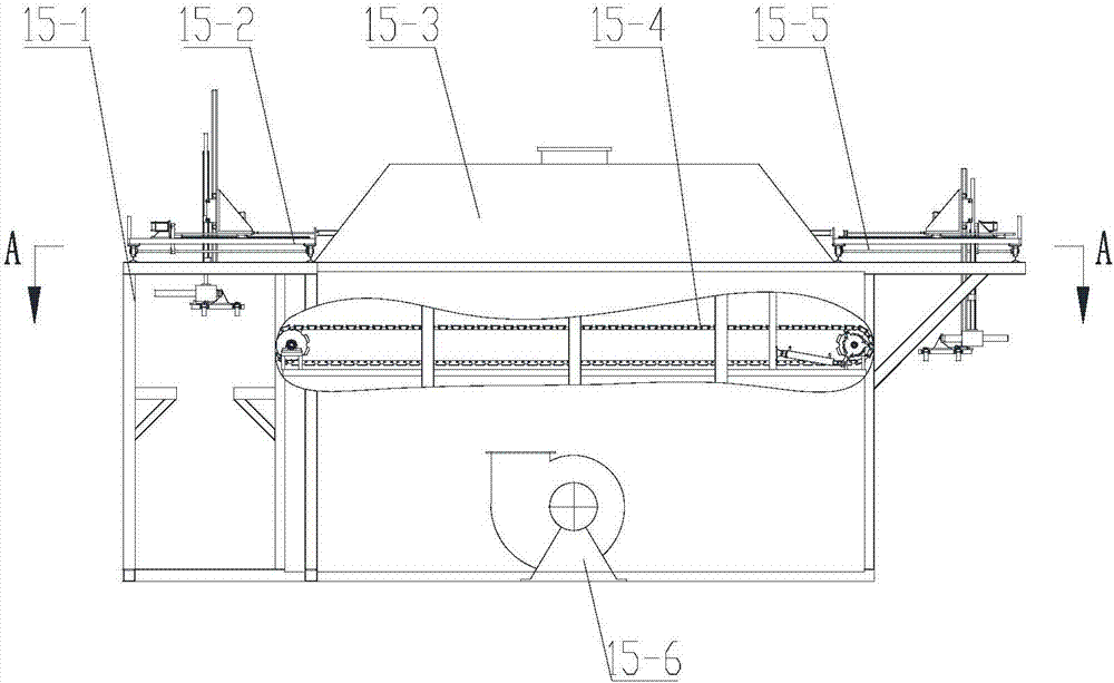
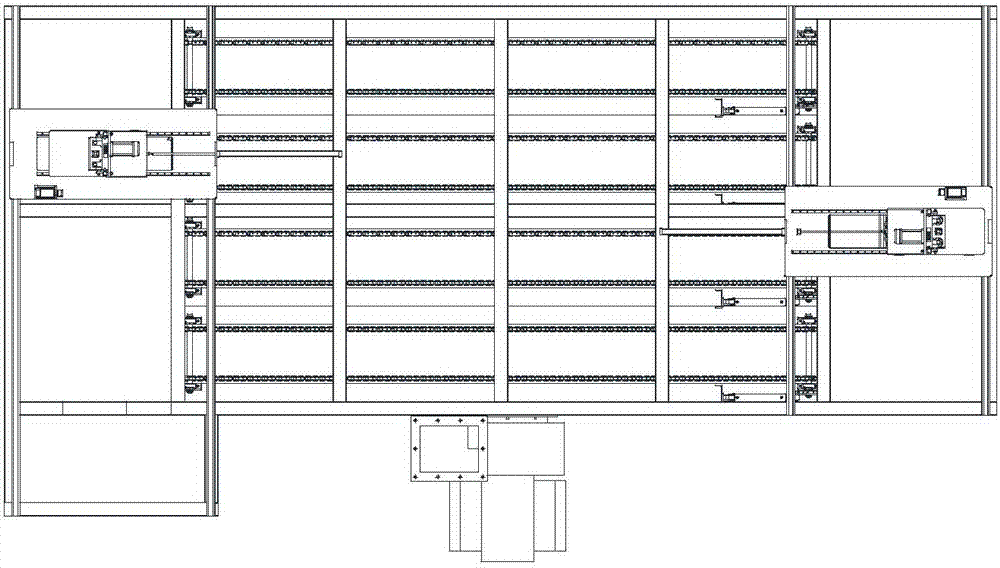
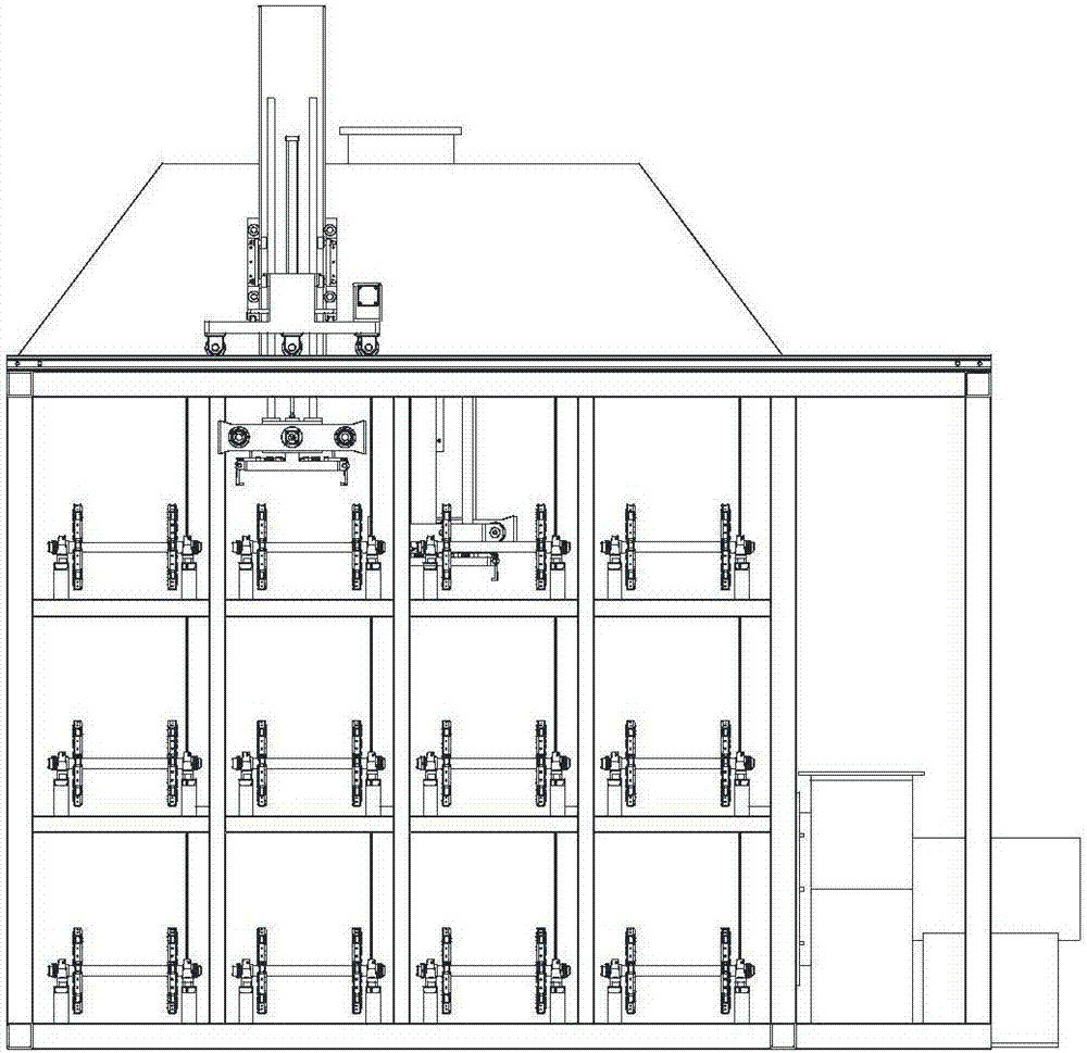
[0030] Present embodiment cooling formwork ( Figure 1-4 ) includes cooling mold frame frame 15-1, cooling mold frame input manipulator 15-2, cooling dust removal system (including suction hood 15-3, cooling fan 15-6), conveyor chain 15-4, cooling mold frame output Box manipulator 15-5, etc., the box-in side of frame 15-1 is installed into box manipulator 15-2, the box-out side is installed with box-out manipulator 15-5, the interior is installed with conveyor chain 15-4, and the top is installed with suction cover 15- 3. Cooling fans 15-6 are installed outside.

[0031] The cooling formwork frame 15-1 is made of square steel, has 3 layers in total, and each layer has 4 entry positions, and each case position is equipped with a conveyor chain 15-4 in the horizontal direction, and each conveyor chain Can place 9 sand boxes. The front an...


PUM


Abstract

The invention discloses a cooling mold frame. The cooling mold frame comprises a frame, a box feeding manipulator, conveying chains and a box discharge manipulator; the box feeding manipulator is mounted on the box feeding side of the frame; the box discharge manipulator is mounted on the box discharge side of the frame; the conveying chains are mounted inside the frame; an air sucking cover is mounted on the frame; the box discharge side of the box feeding manipulator corresponds to the box feeding ends of the conveying chains; the box discharge ends of the conveying chains correspond to the box feeding side of the box discharge manipulator; a cooling fan is mounted on the outer side of the frame; and exhausted air of the cooling fan is introduced into the frame. Cast sand boxes are fed in the automatic cooling mold frame for centralized cooling by the manipulator to reduce the cooling floor area; and the cooled casting sand boxes are shifted out by the manipulator. Castings are fully cooled to achieve better mechanical performance and more precise shape so as to meet the casting process requirements.

Description

technical field [0001] The invention belongs to the technical field of casting, and in particular relates to an automatic cooling frame. Background technique [0002] Due to the large heat capacity of the cast sand box in the casting production process, the cooling in the sand box is relatively slow, and too fast cooling directly affects the quality of the casting. This problem is particularly prominent in summer and autumn. Most of the foundry manufacturers in China directly cool the castings on the spot after casting. Therefore, the floor area is large, and the factory building is full of waste gas and dust generated during the cooling process, causing serious environmental pollution. Contents of the invention [0003] In order to solve the above-mentioned problems existing in the existing domestic foundry industry, reduce the labor intensity of workers, and improve the production level of the domestic foundry industry, the invention discloses a fully automatic cooling...

Claims


Application Information

Patent Timeline
Patent Type & Authority Applications(China)
IPC IPC(8): B22D30/00
CPCB22D30/00
Inventor 邹家春吴平王伟何文晖马新峰
Owner HANGZHOU HUNING ELEVATOR PARTS CO LTD
Why Eureka
Try Eureka