
Prefabricated concrete-filled steel tube and concrete-filled steel tube splicing pier

A technology of reinforced concrete and steel pipe concrete, which is applied in the direction of erecting/assembling bridges, bridges, bridge parts, etc., which can solve traffic flow, work area safety and environmental impact, affect the progress of bridge construction, and have less seismic performance of the whole pier column, etc. problems, to achieve the effect of not affecting normal traffic, low construction noise, and easy on-site splicing

Active Publication Date: 2017-10-27
NORTHEASTERN UNIV
View PDF5 Cites 17 Cited by
  • Summary
  • Abstract
  • Description
  • Claims
  • Application Information

AI Technical Summary

Problems solved by technology

Cast-in-place concrete construction is time-consuming and requires many on-site construction procedures that negatively affect traffic flow, safety in the work area and the environment, especially in complex construction environments, construction spaces, climatic conditions and environmental protection Conditions and other factors seriously affect the progress of bridge construction
[0003] Research on the connection technology between precast concrete piers and foundations, the connection technology between precast concrete sections, the connection between precast concrete sections and cover beams, and the mechanical performance after connection, especially the seismic performance of integral pier columns after connection Relatively few, so its scope of application is still limited

Method used


Image

  • Prefabricated concrete-filled steel tube and concrete-filled steel tube splicing pier
  • Prefabricated concrete-filled steel tube and concrete-filled steel tube splicing pier
  • Prefabricated concrete-filled steel tube and concrete-filled steel tube splicing pier

Examples


Embodiment 1

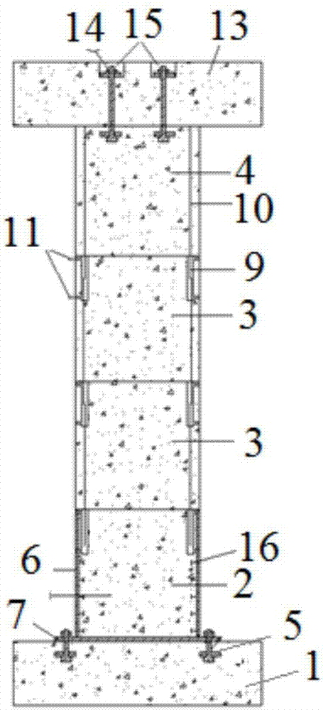
[0069] A prefabricated steel pipe concrete and reinforced concrete bridge pier, such as figure 1 As shown, it includes, from bottom to top, the pier foundation 1, the prefabricated steel pipe concrete section 2, one or more prefabricated reinforced concrete middle sections 3 and the prefabricated reinforced concrete top section 4, wherein the bridge pier foundation 1 and the prefabricated steel pipe concrete The segment 2 is fixedly connected by means of the bottom anchor bolt 5 arranged on the pier foundation 1, between the prefabricated steel pipe concrete segment 2 and the prefabricated reinforced concrete intermediate segment 3, and between a plurality of prefabricated reinforced concrete intermediate segments 3, The prefabricated reinforced concrete middle section 3 and the prefabricated reinforced concrete top section 4 are fixedly connected by means of connecting units.

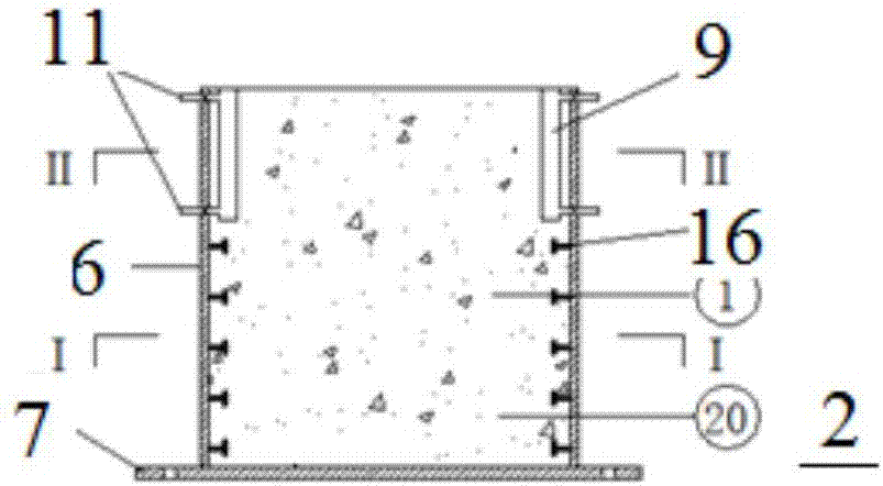
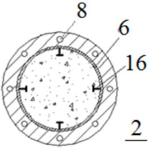
[0070] Specifically, such as Figure 2-Figure 4 shown, where image 3 with Figure 4 for figur...

Embodiment 2

[0093] This embodiment is based on embodiment 1, as shown in the figure, it is different from embodiment 1 in that the cross-sections of prefabricated steel pipe concrete segment 2, prefabricated reinforced concrete middle segment 3 and prefabricated reinforced concrete top segment 4 are all square , that is, the steel pipes in the prefabricated steel pipe concrete segment 2 are also set in a square shape, and of course they can be set in other shapes as required.

[0094] The connecting unit in this embodiment is different from that in Embodiment 1, such as Figure 9 As shown, its connecting unit includes connecting bolts 17, connecting steel plates 18 and connecting anchor tendons 19. Connecting bolt 17 is the top that is embedded in the lower segment, and is arranged at intervals along the edge of the segment. Connecting steel plate 18 is arranged at the lower end of the upper segment. hole, the top of the through hole is reserved with a joint and then poured concrete cavi...

Embodiment 3

[0112] In this embodiment, on the basis of Embodiment 1, the shear connector 16 is set as a steel plate with holes, such as Figure 15 As shown, the steel plate with holes is a strip-shaped steel plate 27 with through holes 21 at equal intervals. The setting of the through holes is conducive to strengthening the connection between the shear connector 16 and the concrete, and improving the ability to work together and coordinate deformation. , steel plates with holes are welded parallel to the inner wall of the steel pipe and arranged at intervals on the inner wall of the steel pipe. Further, steel bars can be arranged in the through holes for better connection, and steel bars are penetrated in the through holes of the perforated steel plates at the same horizontal position along the inner circumference of the steel pipe to form a circle of steel bars around the inner wall or outer wall of the steel pipe. , steel bars can be welded in the through holes to further strengthen the...


PUM


Abstract

The invention relates to a prefabricated concrete-filled steel tube and a concrete-filled steel tube splicing pier. The concrete-filled steel tube assembling pier comprises a pier base, a prefabricating concrete-filled steel tube section, one or more concrete-filled steel tube middle sections and a prefabricating concrete-filled steel tube top section, wherein the pier base is fixedly connected with the prefabricating concrete-filled steel tube section through bottom anchoring bolts arranged on the pier base; the prefabricating concrete-filled steel tube section is fixedly connected with the concrete-filled steel tube middle sections through connecting units; every two concrete-filled steel tube middle sections are fixedly connected through the connecting units; and the concrete-filled steel tube middle sections are fixedly connected with the concrete-filled steel tube top section through the connecting units. According to the concrete-filled steel tube splicing pier disclosed by the invention, each part of assemblies is simple in structure, so that a plant can be convenient to prefabricate, and on-spot splicing is also convenient; the construction operation speed is increased, and on-spot operation strength can also be effectively reduced. The splicing piece disclosed by the invention has the advantages of being high in bearing force, good in compression resistance, good in bending resistance, good in shearing resistance, good in durability, good in vibration resistance and the like.

Description

technical field [0001] The invention belongs to the field of bridge engineering, and in particular relates to a bridge pier assembled with prefabricated steel pipe concrete and reinforced concrete. Background technique [0002] At present, most of the bridges built in my country are composed of cast-in-place reinforced concrete abutments, cast-in-place concrete piers, cast-in-place concrete bridge decks and precast concrete beams. Cast-in-place concrete construction is time-consuming and requires many on-site construction procedures that negatively affect traffic flow, safety in the work area and the environment, especially in complex construction environments, construction spaces, climatic conditions and environmental protection Conditions and other factors seriously affect the progress of bridge construction. [0003] Research on the connection technology between precast concrete piers and foundations, the connection technology between precast concrete sections, the conne...

Claims


Application Information

Patent Timeline
IPC IPC(8): E01D19/02E01D21/00
CPCE01D19/02E01D21/00
Inventor 王连广侯雯峪韩华峰王浩张俊裴家兴
Owner NORTHEASTERN UNIV
Learn More