


Quick Research
Generate reliable direction feasibility study reports for your R&D in just a few steps.

Technical Q&A
Discover and master advanced knowledge NOW. Basics, ideas, possibilities, all at once.

Find Solutions
As an expert in R&D theories, this can generate solutions to your technical problems instantly.

Evaluate Feasibility
Analyze your overall solution with one click, know your potential R&D risks in advance.

Monitor Landscape
Get weekly tech updates, stay abreast of the latest tech innovations and key insights.
Method for driving a clutch
A clutch and transmission technology, applied in the field of clutch control, to improve comfort and save fuel
- Summary
- Abstract
- Description
- Claims
- Application Information
AI Technical Summary
Problems solved by technology
Method used
Image

Examples
Embodiment Construction
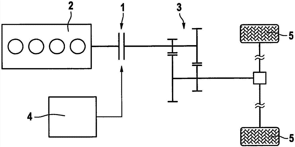
[0021] figure 1 A drive train of a vehicle is shown schematically, wherein the drive train has a controller 4 according to an exemplary embodiment of the invention. The controller 4 acts on the clutch 1 , wherein the clutch 1 is arranged between the drive motor 2 and the transmission 3 in order to selectively enable or prevent a torque transmission between the drive motor 2 and the transmission 3 . The clutch 1 thus comprises a transmission-side part and a motor-side part which are fixedly connected to the transmission 3 or the drive motor 2 respectively and which Can be selectively attached or detached. The transmission 3 is connected to the wheels 5 of the vehicle so as to drive the vehicle through the wheels 5 .
[0022] The clutch 1 is in particular an electronically operated clutch which can be actuated by a driver of the vehicle via a clutch pedal. The clutch pedal is provided in particular to transmit control commands to the controller 4 for actuating the clutch 1 . ...
PUM
 Abstract
Description
Claims
Application Information
 - R&D Engineer
- R&D Manager
- IP Professional
- Industry Leading Data Capabilities
- Powerful AI technology
- Patent DNA Extraction
Browse by: Latest US Patents, China's latest patents, Technical Efficacy Thesaurus, Application Domain, Technology Topic, Popular Technical Reports.
© 2024 PatSnap. All rights reserved.Legal|Privacy policy|Modern Slavery Act Transparency Statement|Sitemap|About US| Contact US: help@patsnap.com