
Rapid construction vibration device based on municipal road project

A municipal road and engineering technology, which is applied in the field of rapid construction leveling devices, can solve the problems of high maintenance costs, hollow ground, shelling, etc.

Inactive Publication Date: 2017-10-24
泉州市西决三维科技有限公司
View PDF1 Cites 3 Cited by
  • Summary
  • Abstract
  • Description
  • Claims
  • Application Information

AI Technical Summary

Problems solved by technology

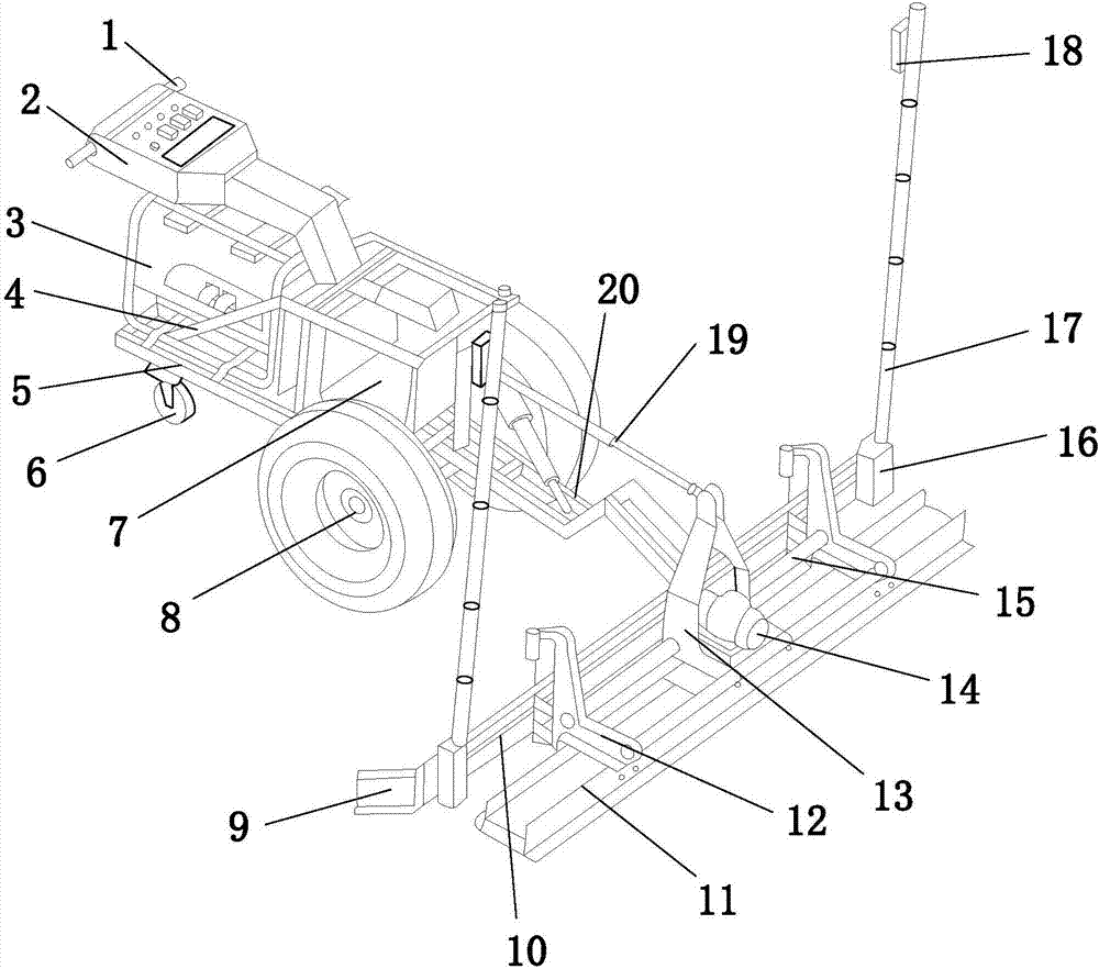
[0005] Aiming at the deficiencies in the prior art, the purpose of the present invention is to provide a rapid construction leveling device based on municipal road engineering, so as to solve the problem that the prior art cannot achieve large-area pavement for road leveling during the construction of municipal roads. Building concrete and ensuring the consistency of the ground elevation will result in a large cumulative error, and the maintenance cost will be high in the later period due to the large number of construction joints, which cannot effectively solve the problems of construction ground cracks, ground hollowing, shelling, cracking, and inequality

Method used


Image

  • Rapid construction vibration device based on municipal road project
  • Rapid construction vibration device based on municipal road project
  • Rapid construction vibration device based on municipal road project

Examples


Embodiment 1

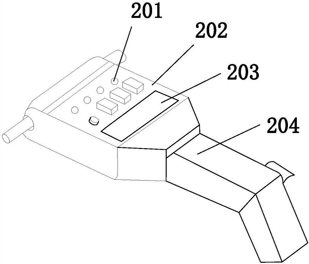
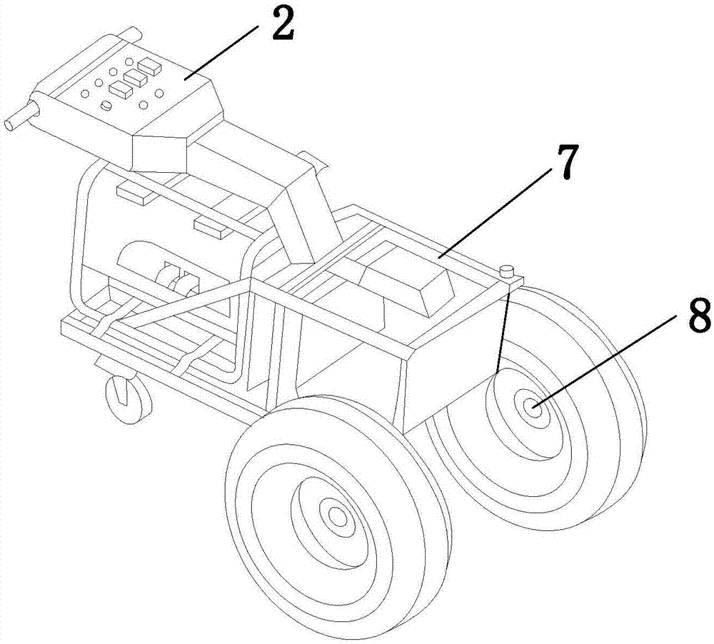
[0034] see Figure 1-Figure 9, the present invention provides a rapid construction leveling device based on municipal road engineering, its structure includes a handle 1, an operator 2, a motor 3, a guardrail 4, a support plate 5, auxiliary wheels 6, a control system 7, and a driving wheel 8 , side plate 9, scraper plate 10, vibrating plate 11, vibrating head 12, fixed protective end 13, vibrating motor 14, limit rod 15, fixed base 16, support column 17, laser receiver 18, hydraulic rod 19, movable Connecting plate 20, laser emission port 21, laser emitter 22, first fixed disk 23, disk fixed rod 24, second fixed disk 25, connecting ring plate 26, buckle 27, support foot 28, bolt 29, The bottom foot 30, the driving wheel 8 is provided with two and is installed on the support plate 5 close to the control system 7 through the connecting shaft, and the motor 3 and the control system 7 are both fixedly installed on the support plate 5 and mechanically connected , one end of the su...

Embodiment 2

[0037] see Figure 1-Figure 10 , the support column 17 includes a reinforcement core 171, a bracket 172, a polyethylene filling layer 173, a reinforcement ring 174, a pipe body 175, and a connecting column 176, and the reinforcement core 171 is installed inside the pipe body 175, and the support 172 Both ends are internally connected to the inside of the pipe body 175, the polyethylene filling layer 173 is filled on the inner wall of the pipe body 175 as an integral structure, and the reinforcing ring 174 is evenly sleeved on the pipe body 175 and is tightly connected to the outer wall of the pipe body 175. touch.

[0038] In order to save the design cost of the present invention, the support column 17 is designed as a pipe body with an internal hollow structure, and the inner wall of the pipe body 175 is filled with a polyethylene filling layer 173. Due to the extremely low low-temperature embrittlement temperature of polyethylene, it can be used in - It is safe to use in th...


PUM

PropertyMeasurementUnit
Widthaaaaaaaaaa
Lengthaaaaaaaaaa

Abstract

The invention discloses a rapid construction leveling device based on municipal road engineering. Vibration plate, leveling head, fixed protective end, vibration motor, limit rod, fixed base, support column, laser receiver, hydraulic rod, movable connection plate, laser emission port, laser emitter, first fixed disc, disc The fixed rod, the second fixed disc, the connecting ring plate, the buckle, the supporting foot, the bolt, and the footing can pave concrete in a large area as a whole and ensure the consistency of the ground elevation. The elevation is not controlled by the formwork, and there will be no cumulative error , The construction joints reduced in large-scale block construction greatly reduce the maintenance cost of the ground in the later stage; multiple operations are integrated together and completed by the machine at one time, improving work efficiency, saving labor, reducing labor and material input, and reducing construction procedures. Speed ​​up construction progress.

Description

technical field [0001] The invention relates to a rapid construction leveling device based on municipal road engineering, and belongs to the technical field of municipal road engineering construction equipment. Background technique [0002] In my country, municipal facilities refer to various buildings, structures, equipment, etc. that are set up within the planning and construction scope of urban areas, towns (townships), and provide residents with paid or unpaid public products and services based on government responsibilities and obligations. The construction of various public infrastructure supporting urban life belongs to the category of municipal engineering, such as common urban roads, bridges, subways, such as various pipelines closely related to life: rainwater, sewage, water supply, reclaimed water, electricity (outside the red line) Partial), telecommunications, heat, gas, etc., as well as the construction of squares, urban greening, etc., all belong to the catego...

Claims


Application Information

Patent Timeline
IPC IPC(8): E01C19/40
CPCE01C19/40
Inventor 陈柔霏谢成忠
Owner 泉州市西决三维科技有限公司
Learn More