Dynamically variable potential energy type laminar flow cooling device

A laminar cooling device, potential energy technology, applied in workpiece cooling device, workpiece surface treatment equipment, metal rolling, etc., can solve the problems of poor cooling effect, turbulent cooling water, long cooling line length, etc.

Pending Publication Date: 2017-10-24
XINJIANG BAYI IRON & STEEL
View PDF0 Cites 1 Cited by
  • Summary
  • Abstract
  • Description
  • Claims
  • Application Information

AI Technical Summary

Problems solved by technology

[0002] At present, the laminar flow cooling device used in the hot rolling technology mainly adopts a high-level fixed water tank to supply water for cooling. In the actual use process, there are mainly problems that the cooling water is easy to form turbulent flow after the pressure reducing valve is installed, the cooling effect is not good, and the cooling is relatively slow. Longer cooling line lengths are required for thicker strips

Method used


Image

  • Dynamically variable potential energy type laminar flow cooling device

Examples


Embodiment Construction

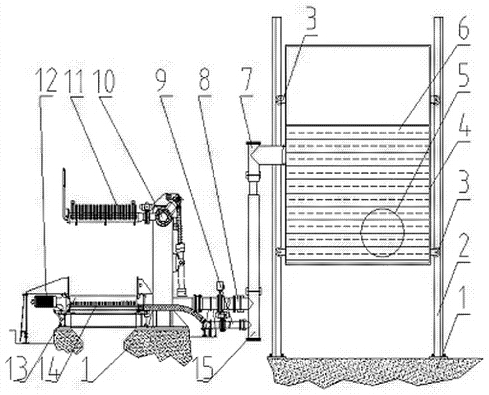
[0010] as attached figure 1 As shown, a dynamic potential energy type laminar flow cooling device mainly includes a foundation 1, a slideway 2, a pulley 3, a water tank 4, a water inlet pipe 5, cooling water 6, a telescopic outlet pipe 7, an upper branch pipe 8, and a lower branch pipe 9 , rotating pipe 10, upper header 11, roller table 13, lower header 14, fixed outlet pipe 15. Water tank 4 is housed between 2 slideways that double as frame, and pulley 3, water inlet pipe 5, flexible water outlet pipe 7 are housed on water tank 4, and cooling water 6 is housed in it. Water tank 4 can realize lifting up and down along slideway 2 by pulley 3. The telescopic water outlet pipe 7 and the fixed water outlet pipe 15 are connected through a sleeve type telescopic seal. The fixed water outlet pipe 15 is through-connected with the upper header 11 and the lower header 14 through the upper branch pipe 8 and the lower branch pipe 9 respectively. Slideway 2, roller table 13, upper heade...


PUM


Abstract

The invention discloses a dynamic potential energy type laminar flow cooling device, which is applied in the technical field of hot continuous rolling; it mainly includes a slideway, a pulley, a water tank, a water inlet pipe, cooling water, a telescopic outlet pipe, an upper branch pipe, and a lower branch pipe , rotating pipe, upper header, roller table, lower header, and fixed outlet pipe; mainly through the connection of the water tank that can be dynamically raised and lowered with the fixed outlet pipe and the telescopic outlet pipe, the upper header and the lower header are supplied with cooling at different stable pressures The water cools the steel strips with different thickness specifications; after the application of the invention, the problems of limited cooling capacity for thicker steel strips, long cooling distance and unstable cooling water pressure can be better avoided.

Description

technical field [0001] The invention relates to a dynamic potential energy type laminar flow cooling device. Background technique [0002] At present, the laminar flow cooling device used in the hot rolling technology mainly adopts a high-level fixed water tank to supply water for cooling. In the actual use process, there are mainly problems that the cooling water is easy to form turbulent flow after the pressure reducing valve is installed, the cooling effect is not good, and the cooling is relatively slow. Longer cooling line lengths are required for thicker strips. Contents of the invention [0003] The object of the present invention is to provide a dynamic potential energy type laminar flow cooling device, which can avoid the turbulent flow of cooling water caused by the pressure reducing valve by dynamically adjusting the potential energy pressure of the cooling water; meanwhile, it can also reduce the construction length of the cooling line. [0004] The purpose of...

Claims


Application Information

Patent Timeline
IPC IPC(8): B21B45/02
CPCB21B45/0218
Inventor 范振磊
Owner XINJIANG BAYI IRON & STEEL
Why Eureka
Try Eureka