Crankshaft structure

Active Publication Date: 2015-01-29
HONDA MOTOR CO LTD
View PDF2 Cites 0 Cited by
  • Summary
  • Abstract
  • Description
  • Claims
  • Application Information

AI Technical Summary

Benefits of technology

The invention aims to create a crankshaft that is lighter, stronger, and more rigid while improving its lubrication capacity.

Problems solved by technology

However, further weight reduction of a crankshaft while increasing strength and rigidity of the crankshaft is required.

Method used


Image

  • Crankshaft structure
  • Crankshaft structure
  • Crankshaft structure

Examples


Embodiment Construction

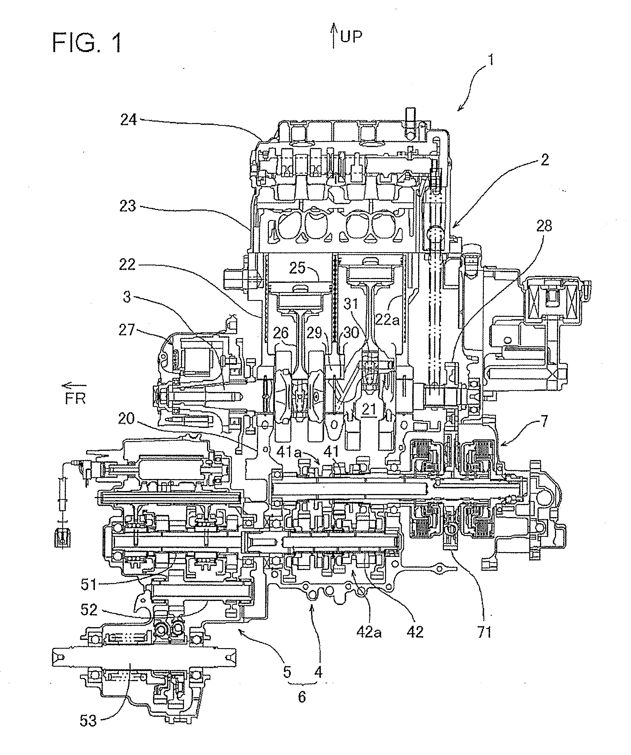
[0025]FIG. 1 is a developed view in vertical cross section of a power unit equipped with a crankshaft structure in accordance with an embodiment of the present invention. In the following description, the orientation such as “front”, “rear”, “upper”, “lower” and the like shall be determined based on the orientation of a vehicle such as all terrain vehicle (not shown in the drawing) on which a power unit 1 according to this embodiment is mounted in the position as shown in FIG. 1. In FIG. 1, an upper side of the drawing is an upper side of the vehicle and a left side of the drawing is a forward side of the vehicle.

[0026]The power unit 1 is mounted on the vehicle with a crankshaft 3 of an internal combustion engine 1 extending in a forward and backward direction of the vehicle. An output shaft 53 (a speed change driven shaft) of the power unit 1 projects in front and in the rear. The rotational motive power of the output shaft 53 is transmitted through a front drive shaft and a front ...


PUM


Abstract

A crankshaft structure includes a crank pin section, a crank journal section, and a counter weight section arranged between the crank pin section and the crank journal section in a direction of a crankshaft. A crank arm section connecting the crank pin section and the crank journal section is formed with each of lateral edge portions extending substantially along a circumscribed tangential line connecting a base of the crank pin section and a base of the crank journal section when viewed in the direction of the crankshaft. Each of the lateral edge portions of the crank arm section includes an edge groove having a length extending between a central axis of the crank pin section and a central axis of the crank journal section when viewed in a direction to cross the crankshaft. The edge groove has a groove bottom portion formed between two reinforcing ribs.

Description

BACKGROUND OF THE INVENTION[0001]1. Field of the Invention[0002]The present invention relates to a crankshaft structure which is reduced in weight.[0003]2. Description of Related Art[0004]A crankshaft structure in which a crank arm holding a crank pin section is formed with cutouts at both lateral edge portions thereof on each of the crank pin section side and a crank journal section side so as to be reduced in weight is disclosed in Japanese Patent Application Laid-Open Publication No. H04-262147, for instance. However, further weight reduction of a crankshaft while increasing strength and rigidity of the crankshaft is required.BRIEF SUMMARY OF THE INVENTION[0005]In view of the above prior art, the present invention has an objective of providing a crankshaft structure that is reduced in weight while making it possible to increase strength and rigidity of the crankshaft and that is improved in lubrication capacity thereof.[0006]In order to achieve the above described object, accordi...

Claims


Application Information

Patent Timeline
IPC IPC(8): F16C3/06F16C3/20
CPCF16C3/20F16C3/06F16C2360/22F16C3/08F16C3/22F16C3/14Y10T74/2183
Inventor HARADA, MOTOKINIINO, TADASHIKAMIYA, MITSUYOSHI
Owner HONDA MOTOR CO LTD
Why Eureka
Try Eureka