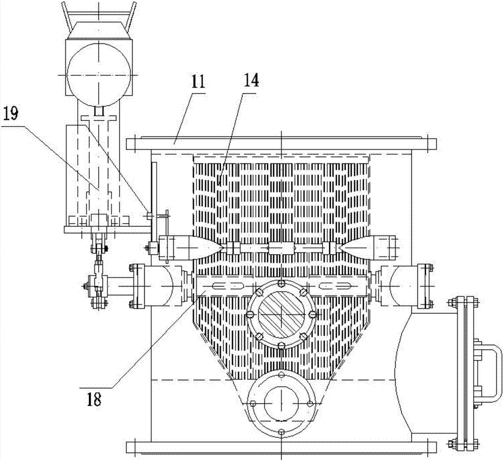
Rubber-ball online monitoring system
A monitoring system and rubber ball technology, which is applied in the direction of non-rotating equipment cleaning, cleaning heat transfer devices, lighting and heating equipment, etc., can solve the problem of difficult operation of the rubber ball cleaning system, high labor intensity of operators, and affect the operation of the rubber ball system Effect and system energy consumption and other issues, to achieve the effect of simple structure, low manufacturing cost and ensuring accuracy
Inactive Publication Date: 2017-09-29
JIANGSU ZHONGNENG POWER EQUIP
View PDF0 Cites 2 Cited by
- Summary
- Abstract
- Description
- Claims
- Application Information
AI Technical Summary
Problems solved by technology
[0003] At present, the cleaning of rubber balls generally adopts the method of regular shutdown and manual counting of balls. The operation status of the rubber ball cleaning system can only be judged through the observation window set by the rubber ball system based on the subjective judgment of the human eye and offline manual counting of the balls. The labor intensity of the operators Larger, it is difficult to quickly and accurately judge the running status of the rubber ball cleaning system, which affects the running effect and system energy consumption of the rubber ball cleaning system
Method used
View moreImage
Smart ImageViewing Examples
Examples
Embodiment Construction
[0023] In order to make the technical solution of the present invention clearer, the present invention will be further described below in conjunction with the accompanying drawings. Any solution obtained by equivalent replacement and conventional reasoning of the technical features of the technical solution of the present invention falls within the protection scope of the present invention.
Login to View More PUM
 Abstract
The invention relates to an on-line monitoring system for rubber balls, which includes a ball collection net, a ball loading room, a rubber ball collector and a rubber ball pump. The ball port is connected, the ball outlet of the rubber ball collector is connected to the rubber ball pump through the third pipeline, the third pipeline is equipped with an electric ball valve and a reducing pipe, and the rubber ball pump is connected to the ball chamber through the fourth pipeline , the fourth pipeline is provided with a pressure gauge, the present invention has good stability, accurate counting, simple structure and low manufacturing cost.
Description
technical field [0001] The invention relates to an on-line monitoring system for rubber balls. Background technique [0002] As we all know, during the power generation process, the power plant mainly uses the rubber ball cleaning device to clean the condenser to prevent the dirt on the cooling tube wall of the condenser from affecting the heat exchange efficiency of the condenser, resulting in a decrease in the vacuum degree of the unit and increasing the coal consumption of power generation. If fouling occurs on the pipe wall, it will seriously affect the normal operation of the cleaning device. The existing condenser rubber ball cleaning device is made up of components such as a ball collecting net, a rubber ball conveying pump, a ball loading chamber, a controller, a rubber ball and a circulation pipeline. It periodically uses high-pressure water to squeeze clean rubber balls larger than the inner diameter of the cooling tube of the condenser through the cooling tube, r...
Claims
Login to View More Application Information
Patent Timeline
 Patent Type & Authority Applications(China)
IPC IPC(8): F28G1/12F28G15/00
CPCF28G1/12F28G15/00
Inventor 丁为平陈克祥戴永志顾斌张达健
Owner JIANGSU ZHONGNENG POWER EQUIP
- R&D Engineer
- R&D Manager
- IP Professional
- Industry Leading Data Capabilities
- Powerful AI technology
- Patent DNA Extraction
Learn More Browse by: Latest US Patents, China's latest patents, Technical Efficacy Thesaurus, Application Domain, Technology Topic, Popular Technical Reports.
© 2024 PatSnap. All rights reserved.Legal|Privacy policy|Modern Slavery Act Transparency Statement|Sitemap|About US| Contact US: help@patsnap.com


