Ammonia-process desulfurization method and device for chamber-division ammonification
An ammonia desulfurization and compartmentalized technology, which is applied in separation methods, chemical instruments and methods, dispersed particle separation, etc., and can solve problems such as ammonia escape.
- Summary
- Abstract
- Description
- Claims
- Application Information
AI Technical Summary
Problems solved by technology
Method used
Image
Examples
Embodiment 1
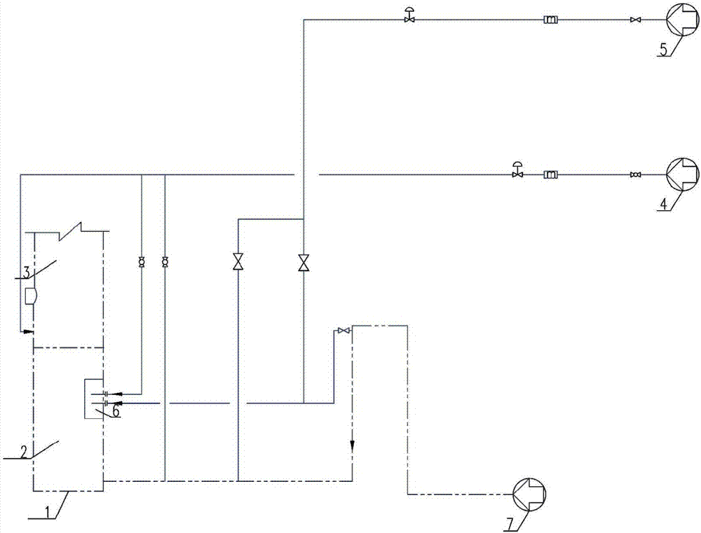
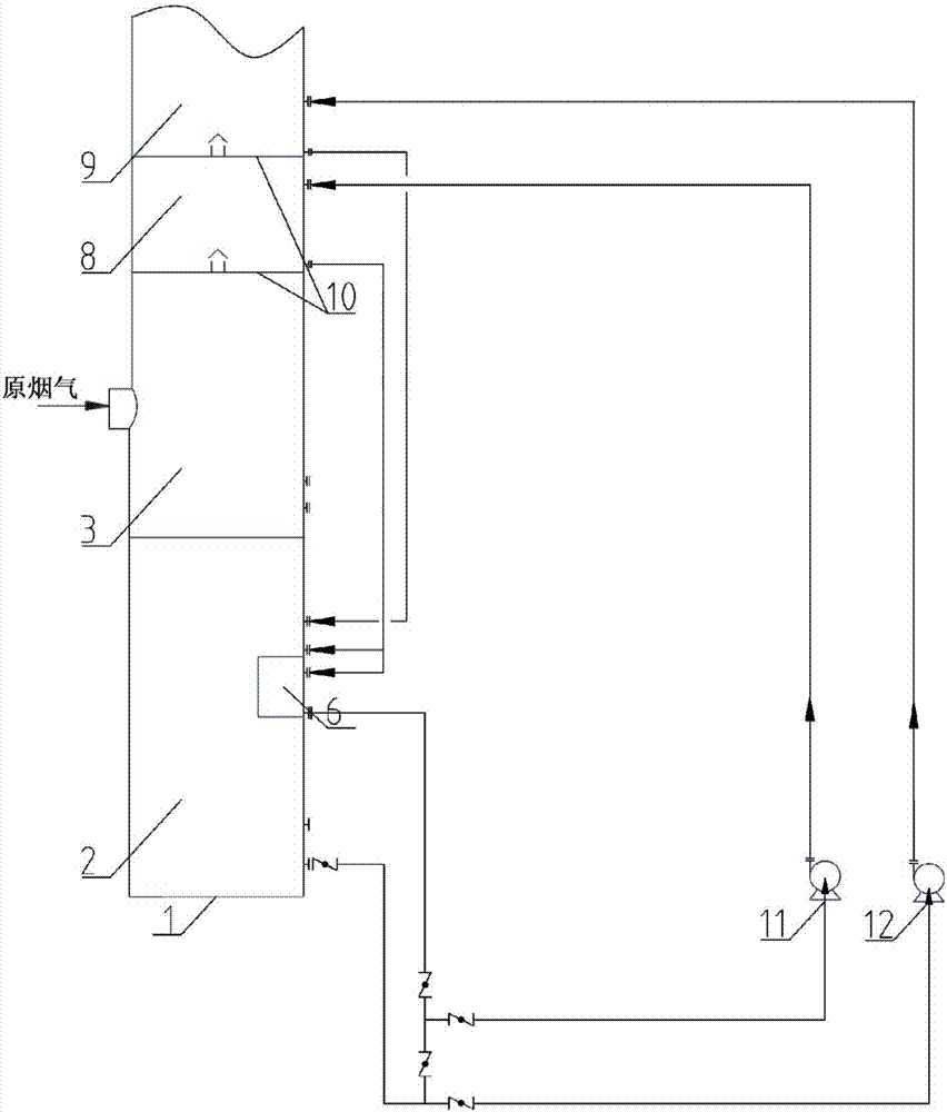
[0065] The flue gas from the coal combustion process is subjected to ammonia desulfurization using the inventive device, wherein the device is basically as follows Figure 1-3 As shown in , except that the oxidation chamber and the ammoniation chamber are provided by two tanks outside the absorption tower, the two tanks are provided with DN500 connecting pipes in the middle; the circulating liquid from the lower outlet of the ammoniation chamber enters the primary spray absorption section In the upper part, the circulating liquid from the lower outlet of the oxidation chamber enters the upper part of the secondary spray absorption section; the reflux liquid from the primary and secondary spray absorption sections joins at the gas-liquid separator between the cooling concentration section and the primary spray absorption section , a total of 2700m 3 / h, 60% of the reflux liquid goes to the ammonia chamber, and 40% of the reflux liquid goes to the oxidation chamber; the liquid a...
Embodiment 2
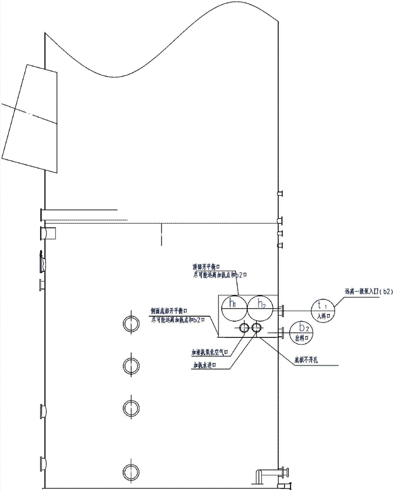
[0069] Repeat the test of Example 1, except that the oxidation chamber and the ammoniation chamber are arranged in the same groove with a diameter of 5.5m, the cross-sectional area of the ammoniation chamber is 18% of the cross-sectional area of the groove, and the top of the ammoniation chamber is larger than that in the oxidation chamber. The liquid level is 1m lower; 13 balance ports are opened on the lower part of the side of the ammonia addition chamber, and 22 balance holes are opened on the top plate, with a single hole size of 80×80mm. Semi-cylindrical shape with a volume of 27m 3 , the volume of the oxidation chamber is 220m 3 ; The spray liquid from the primary and secondary spray absorption sections is combined, wherein 70% of the combined reflux liquid is combined with 2522kg / h of 20% ammonia water and then enters the ammonia addition chamber, and the rest of the reflux liquid enters the oxidation chamber.
[0070] The pH of the circulating liquid taken out fr...
Embodiment 3
[0073] Adopt the device of embodiment 1 to test, except that the oxidation chamber and the ammonia addition chamber are arranged in the same tank with a diameter of 6m, the cross-sectional area of the ammonia addition chamber is 20% of the cross-sectional area of the tank, and the top of the ammonia addition chamber is larger than that of the oxidation chamber. The liquid level in the tank is 1.5m lower; 8 balance ports are opened on the lower part of the side of the ammonia addition chamber, and 13 balance holes are opened on the top plate. The size of each hole is 100×100mm. Room volume is 25m 3 , located in the middle of the tank, it is a horizontal tank type, and the volume of the oxidation chamber is 228m 3 ; The spray liquid from the primary and secondary spray absorption sections is not combined, and is sent to the ammoniation chamber and the oxidation chamber respectively, and the flow rate of the reflux liquid to the ammoniation chamber is 1700m 3 / h, and the ref...
PUM
 Abstract
Description
Claims
Application Information
 - R&D Engineer
- R&D Manager
- IP Professional
- Industry Leading Data Capabilities
- Powerful AI technology
- Patent DNA Extraction
Browse by: Latest US Patents, China's latest patents, Technical Efficacy Thesaurus, Application Domain, Technology Topic, Popular Technical Reports.
© 2024 PatSnap. All rights reserved.Legal|Privacy policy|Modern Slavery Act Transparency Statement|Sitemap|About US| Contact US: help@patsnap.com


