Liquid light conduction device for intervention

A light conduction, liquid technology, applied in the field of interventional radiology, which can solve the problem that the catheter cannot transmit light energy.

Active Publication Date: 2017-09-29
尚华
View PDF8 Cites 4 Cited by
  • Summary
  • Abstract
  • Description
  • Claims
  • Application Information

AI Technical Summary

Problems solved by technology

[0005] In view of this, the catheter of the Seldinger arterial cannulation technology cannot transmit light energy, and the photodynamic therapy cannot reach the lesion in the body. The present invention proposes a liquid light conduction device for intervention, which constitutes the simultaneous delivery of light energy and drugs. The pipeline, drugs and laser approach the treatment from the vascular channel inside the tumor, which can make the photosensitizer and laser directly act on the deep tumor, enhance the therapeutic effect and reduce the side effects

Method used


Image

  • Liquid light conduction device for intervention
  • Liquid light conduction device for intervention
  • Liquid light conduction device for intervention

Examples


Embodiment 1

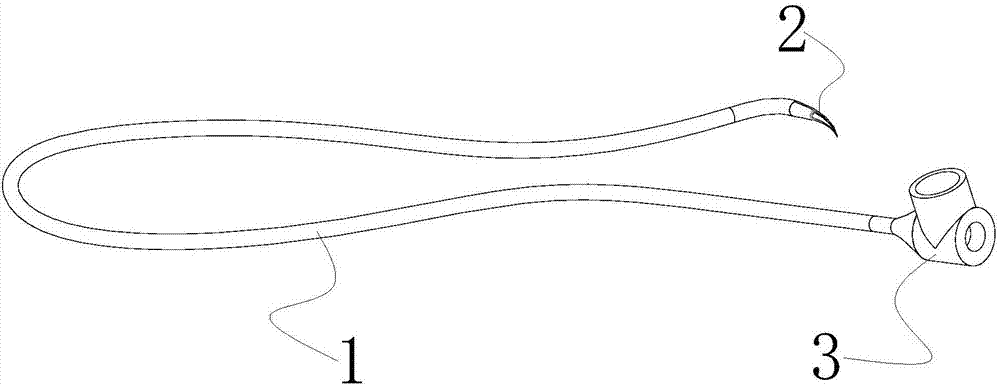
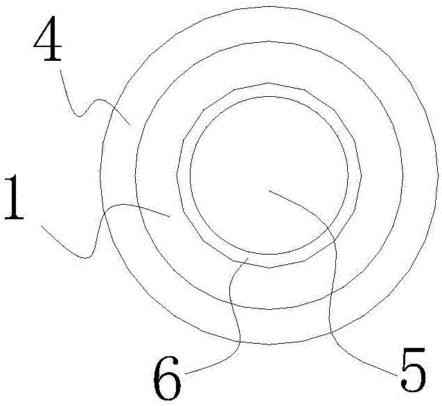
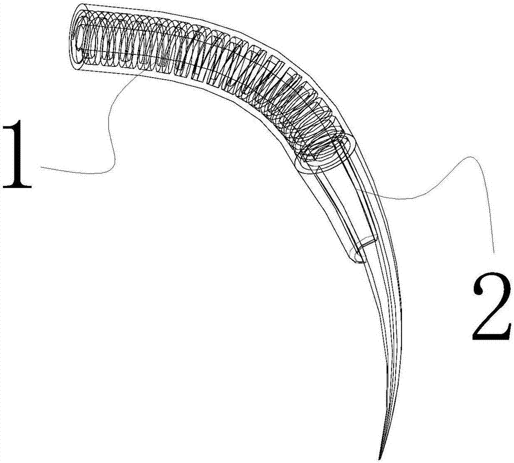
[0041] Such as Figure 1-11As shown, a liquid light transmission device for intervention includes a catheter 1, a tail sheath 2 and a liquid-laser coupler 3, and its main body is a catheter 1 made of metal, such as made of stainless steel; the inside of the catheter 1 It is a cavity 5 structure, and the liquid medium and laser can be transmitted in the cavity 5. The liquid medium can be physiological saline, photosensitizer, etc.; the inner wall of the catheter 1 is coated with a metal reflective layer 6 to reduce the loss of laser transmission in the catheter 1 , then the liquid medium can be transmitted in the catheter, and the laser can be transmitted in the liquid wrapped in the metal reflective layer 6 and released to the diseased part through the tail sheath 2 . The periphery of the catheter is provided with a hydrophilic layer 4 that wraps the catheter, and the hydrophilic layer 4 can enhance the blood permeability of the device and reduce blood resistance; the material...

Embodiment 2

[0056] The catheter in Embodiment 1 can also be made of non-metallic materials, such as polymer or quartz.

[0057] During specific implementation, a 306 stainless steel conduit with an inner diameter of 0.3mm and an outer diameter of 0.5mm can be used as the main body, the inner wall is silver-plated, the outer wall is cut into a circular spiral pattern cutting, and the cutting depth is less than 0.2mm; the liquid in the catheter cavity 5 refracts The ratio is 1.33, and the laser is transmitted to the tail sheath under the reflection of the liquid and the inner wall of the catheter. The tail sheath is tightly wrapped on the outer wall of the catheter with a transparent heat-shrinkable polymer material, the tail sheath is curved and gradually becomes thinner, and the tail sheath and the catheter can be integrally formed; the tip of the tail sheath, that is, the diameter of the outermost free end can be compared with the The diameter of the cavity 5 in the catheter is the same,...


PUM


Abstract

The present invention relates to a liquid light conduction device for intervention. The device comprises a conduit with an internal portion which is a cavity, one end of the conduit is provided with a tail sheath, and the other end of the conduit is provided with a liquid-laser coupler capable of injection of liquid medium and conduction of laser; the tail sheath is provided with an outlet; a metal reflection layer is arranged at the inner wall of the conduit, the liquid medium can be transmitted in the conduit, and the laser can be transmitted in the liquid coated with the metal reflection layer and can be transmitted out through the tail sheath. The liquid light conduction device for intervention can introduce laser and liquid medicine into the artery to directly reach diseased regions through adoption of the Seldinger arterial cannula technology, the laser is conducted through the liquid medicine conduit coated with the metal reflection layer, and the medicine and the laser can reach the diseased regions through blood vessels in a tumour for treatment to allow a photosensitizer and the laser to be directly effected on deep tumors so as to enhance the treatment effect and relieve toxic and side effects.

Description

technical field [0001] The invention relates to the technical field of interventional radiology in the medical field, in particular to a liquid light conduction device for intervention. Background technique [0002] In 1953, Seldinger first reported the method of percutaneous femoral artery puncture with a puncture needle. This closed catheterization technology does not block the blood flow of the inserted blood vessel (artery or vein), has less bleeding, and reduces local complications from 8% to 1.3%, so that catheter technology is widely used in diagnostic radiology and interventional radiology, that is, Surgical radiology plays a wide-ranging role in different fields. For example, external carotid artery cannulation, which is widely used at present, can be treated with chemical drugs before head and neck malignant tumors. , Pushed to the tumor site from the artery, and then release the drug slowly, the curative effect is better. After the tumor is confined or shrunk, ...

Claims


Application Information

Patent Timeline
Patent Type & Authority Applications(China)
IPC IPC(8): A61N5/06A61M31/00
CPCA61M31/00A61N5/0601A61N5/062A61N2005/0602A61N5/067
Inventor 尚华吕新杰王智文
Owner 尚华
Why Eureka
Try Eureka