An online autocatalytic denitrification device for sintering dust

A self-catalysis and denitration technology, applied in chemical instruments and methods, separation methods, dispersed particle separation, etc., can solve the problems of occupying catalyst surface active points, accelerating catalyst pore blockage, accelerating catalyst poisoning effect, etc., and saving denitration equipment investment. , the effect of increasing the catalyst concentration and reducing the cost of denitration

Active Publication Date: 2020-05-19
武汉钢铁有限公司 +2
View PDF4 Cites 0 Cited by
  • Summary
  • Abstract
  • Description
  • Claims
  • Application Information

AI Technical Summary

Problems solved by technology

Explored its mechanism and found that when there is SO in the flue gas 2 When, O 2 can be oxidized to SO 3 , SO 3 Reacting with metal oxides will generate sulfate and ammonium sulfate will adhere to the surface of the catalyst. It is difficult to desorb under low temperature conditions, occupying the active points on the catalyst surface and reducing the activity of the catalyst.
The presence of water can accelerate the poisoning effect of the catalyst. On the one hand, it is due to the water vapor and NH on the surface of the catalyst. 3 The competitive adsorption between NO and NO, on the other hand, may be due to the presence of water vapor that accelerates the deposition of ammonium sulfate on the surface of the catalyst and accelerates the blockage of the catalyst pores, thereby further reducing the activity of the catalyst.
[0005] In order to reduce denitrification energy consumption, the reaction temperature of the low-temperature SCR denitrification catalyst requires its reaction device to be placed before the desulfurization device, so the low-temperature SCR denitrification catalyst's anti-SO 2 The poisoning ability must be an important factor affecting its life, and the anti-SO 2 Poisoning ability is not as good as expected

Method used


Image

  • An online autocatalytic denitrification device for sintering dust
  • An online autocatalytic denitrification device for sintering dust
  • An online autocatalytic denitrification device for sintering dust

Examples


Embodiment 1

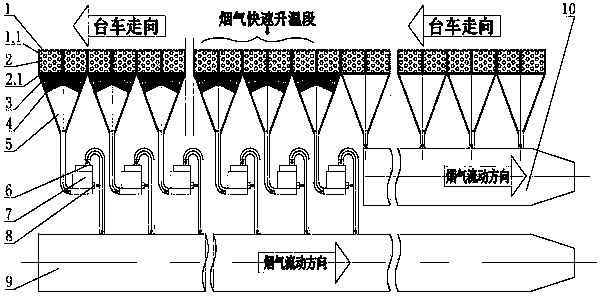
[0028] Example 1: see figure 1 , including a sintering machine 1, a bellows 5 is arranged under the trolley 1.1 of the sintering machine 1, and the outlet at the bottom of the bellows 5 is connected to the main flue, and the sintering machine 1 is sequentially divided into ignition section, head section, There are 4 areas of the flue gas rapid heating section and the tail section, and the bellows 5 below the tail section to the flue gas rapid heating section area are equipped with liquid ammonia nozzles 3. The liquid ammonia nozzle 3 is located on the upper part of the bellows 5, and is arranged along the circumferential direction of the side wall of the bellows 5, and the nozzle outlet is inclined upward. The main flue is composed of a high temperature flue gas main flue 9 and a low temperature flue gas main flue 10 . The outlet of the bellows 5 below the tail section and the rapid heating section of the flue gas is connected to the main flue 4 of high temperature flue gas t...

Embodiment 2

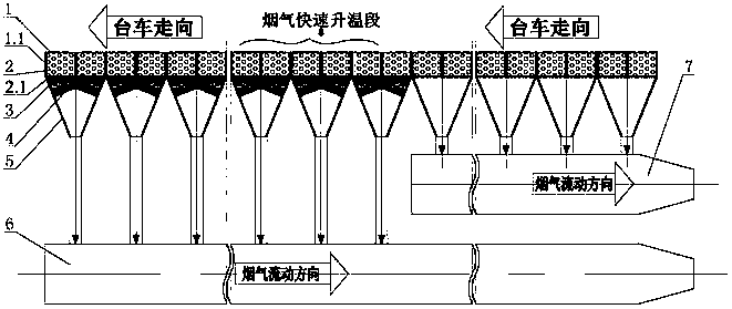
[0043] see figure 2 , without the fluidized bed reactor 7, the sintered flue dust is directly sent into the high temperature flue gas main flue 9 without passing through the fluidized bed reactor 7, and the rest are the same as in Example 1.

Embodiment 3

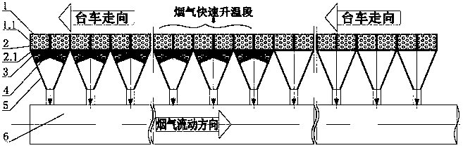
[0045] see image 3 , without the low temperature flue gas main flue 10 and the fluidized bed reactor 7, all the sintered soot in the bellows 5 is directly fed into the high temperature flue gas main flue 9, and the rest are the same as in Example 1.


PUM


Abstract

The invention discloses a sintering smoke online self-catalyzing denitrifying device, which solves the problems of large investment, high running cost and the like in the existing sintering smoke denitrifying system. The sintering smoke online self-catalyzing denitrifying device adopts the technical scheme that the sintering smoke online self-catalyzing denitrifying system comprises a sintering machine, wherein air bellows are arranged under a trolley of the sintering machine; an exit of the bottom part of each air bellow is communicated with a main flue; the sintering machine is sequentially provided with an ignition section, a machine head section, a flue gas quick heating section and a machine tail section along the moving direction of the trolley; liquid ammonia spray nozzles are respectively arranged in the air bellows under the machine tail section to the flue gas quick heating section area. The sintering smoke online self-catalyzing denitrifying system has the advantages that the system is simple, the additional purchase of the catalyst is avoided, the land occupation area is small, and the equipment investment and running cost are low.

Description

technical field [0001] The invention relates to a flue gas denitrification device in the field of environmental protection, in particular to an on-line autocatalytic denitration device for sintering fume. Background technique [0002] In countries with developed steel industry, such as Japan, the United States and Germany, sintering flue gas has undergone desulfurization and denitrification treatment. Domestic sintering flue gas desulfurization has been basically completed in the "Twelfth Five-Year Plan", but the engineering application of denitrification technology has just started. Activated carbon (coke) adsorption and selective catalytic reduction (S-SCR) are two technologies that can be applied in engineering and have actual achievements in sintering flue gas denitrification technology, but the shortcomings of the two processes are obvious. Activated carbon (coke) adsorbs SO 2 , and use NH 3 Reduction of NOx can achieve simultaneous desulfurization, denitrification a...

Claims


Application Information

Patent Timeline
Patent Type & Authority Patents(China)
IPC IPC(8): B01D53/90B01D53/56
CPCB01D53/343B01D53/8631B01D53/90B01D2251/2062B01D2255/20738B01D2258/0283
Inventor 杨超吴高明丁翠娇吴晓晖卫书杰
Owner 武汉钢铁有限公司
Why Eureka
Try Eureka