Optical current transformer with anti-vibration function and anti-vibration interference method realized by using the current transformer
A current transformer, anti-vibration interference technology, applied in voltage/current isolation, measurement using digital measurement technology, etc., can solve problems affecting the accuracy of output results, external vibration interference of optical current transformers, etc., to improve the accuracy rate , the effect of reducing the impact
- Summary
- Abstract
- Description
- Claims
- Application Information
AI Technical Summary
Problems solved by technology
Method used
Image
Examples
specific Embodiment approach 1
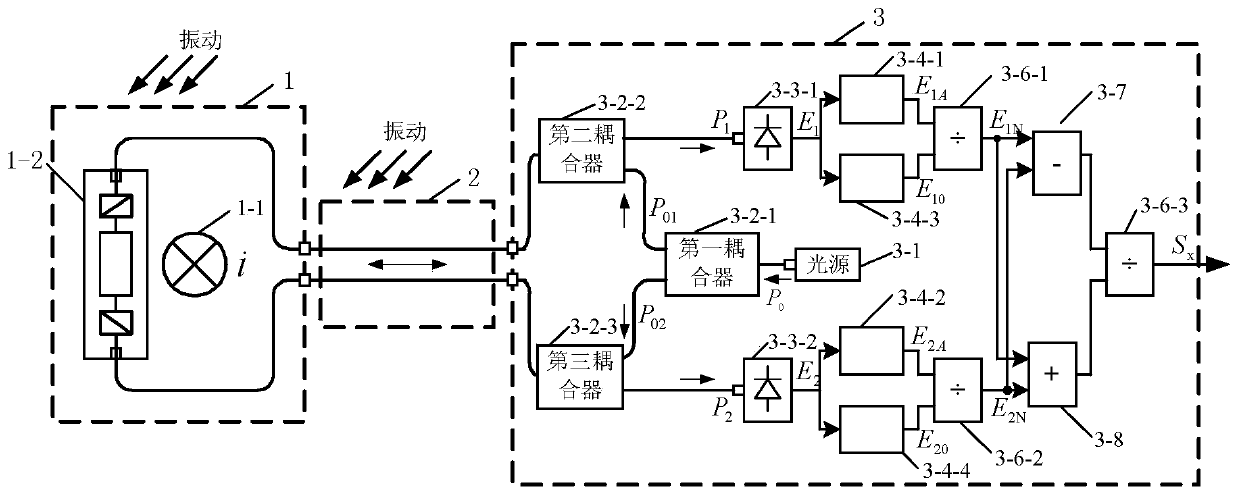
[0041] Specific implementation mode one: see figure 1 Describe this embodiment mode, an optical current transformer with anti-vibration function described in this embodiment mode, which includes a primary processing part 1, a transmission fiber part 2 and a secondary processing part 3;
[0042] Two-way analog optical information exchange is performed between the primary processing part 1 and the secondary processing part 3 through the transmission fiber part 2,
[0043] The primary processing part 1 is used to induce the current signal, and load the induced current signal on the carrier light generated by the secondary processing part 3, and the secondary processing part 3 performs anti-vibration processing on the carrier light loaded with the induced current, thereby obtaining the processed The subsequent current information.
[0044] In this embodiment, the present invention effectively eliminates or weakens the influence of vibration interference on the output results throug...
specific Embodiment approach 2
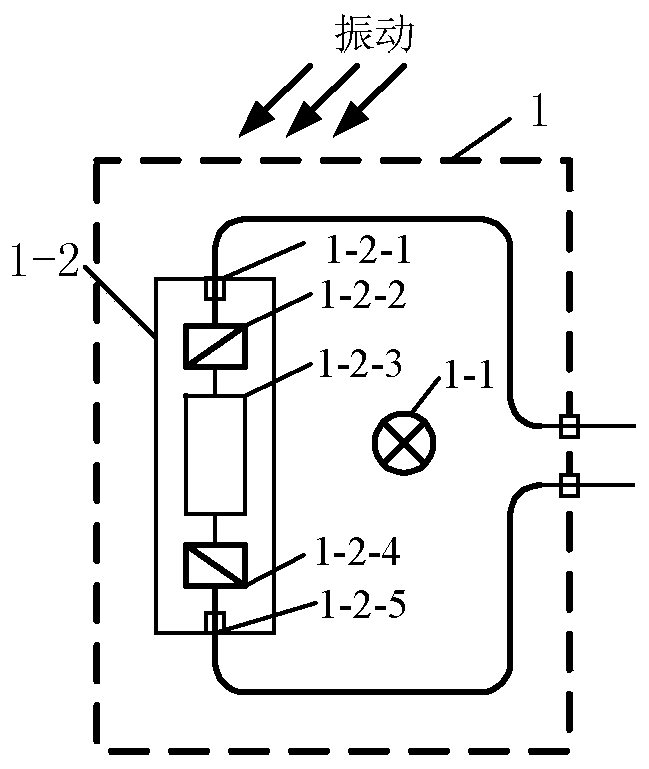
[0045] Specific implementation mode two: see figure 1 Describe this embodiment. The difference between this embodiment and the optical current transformer with anti-vibration function described in Embodiment 1 is that the primary processing part 1 includes a conductor 1-1 and a magneto-optical glass type current sensor 1 -2;
[0046] The secondary processing part 3 includes a light source 3-1, a first coupler 3-2-1, a second coupler 3-2-2, a third coupler 3-2-3, a first photodetector 3-3- 1. The second photodetector 3-3-2, the first low-pass filter 3-4-1, the second low-pass filter 3-4-2, the third low-pass filter 3-4-3, the first low-pass filter Four low-pass filters 3-4-4, first divider 3-6-1, second divider 3-6-2, third divider 3-6-3, subtractor 3-7 and adder 3 -8;
[0047] Magneto-optic glass type current sensor 1-2, used for collecting current information of conductor 1-1,
[0048] The light emitted by the light source 3-1 is split into two beams with equal success ra...
specific Embodiment approach 3
[0055] Specific implementation mode three: see figure 1 This embodiment is described. The difference between this embodiment and the optical current transformer with anti-vibration function described in the second embodiment is that the first coupler 3-2-1, the second coupler 3- Both 2-2 and the third coupler 3-2-3 are 3dB fiber couplers.
PUM
 Abstract
Description
Claims
Application Information
 - R&D
- Intellectual Property
- Life Sciences
- Materials
- Tech Scout
- Unparalleled Data Quality
- Higher Quality Content
- 60% Fewer Hallucinations
Browse by: Latest US Patents, China's latest patents, Technical Efficacy Thesaurus, Application Domain, Technology Topic, Popular Technical Reports.
© 2025 PatSnap. All rights reserved.Legal|Privacy policy|Modern Slavery Act Transparency Statement|Sitemap|About US| Contact US: help@patsnap.com


