
Digital-analog hybrid heterodyne detection receiving device and data processing method adopted by same

A digital-analog hybrid and heterodyne detection technology is applied in electromagnetic receivers, digital transmission systems, and modulated carrier systems. It can solve the problems of difficult hardware implementation and large Doppler frequency deviation, and achieve low phase noise and frequency Large dynamic range and the effect of carrier synchronization

Active Publication Date: 2017-09-19
SHANGHAI ENG CENT FOR MICROSATELLITES
View PDF9 Cites 34 Cited by
  • Summary
  • Abstract
  • Description
  • Claims
  • Application Information

AI Technical Summary

Problems solved by technology

[0004] One of the objectives of the present invention is to provide a Doppler pre-compensation method for the problem of large Doppler frequency deviation in space laser communication
[0005] The second object of the present invention is to realize carrier synchronization and clock synchronization by ultra-high-speed analog-to-digital conversion devices and converted multi-bit parallel high-speed digital signal processing in the digital domain for digital homodyne coherent reception technology, which leads to great difficulty in hardware implementation, etc. problem, providing a digital-analog hybrid solution

Method used


Image

  • Digital-analog hybrid heterodyne detection receiving device and data processing method adopted by same
  • Digital-analog hybrid heterodyne detection receiving device and data processing method adopted by same
  • Digital-analog hybrid heterodyne detection receiving device and data processing method adopted by same

Examples


Embodiment Construction

[0044] Hereinafter, the spirit and essence of the present invention will be further elaborated in conjunction with the drawings and embodiments.

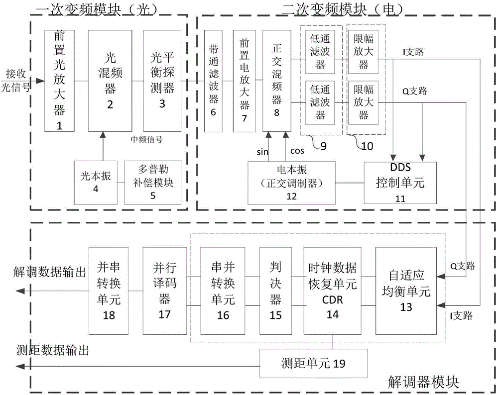
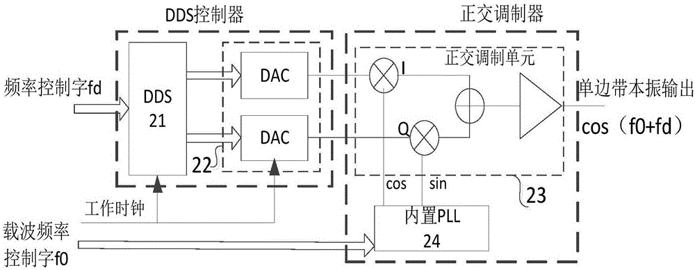
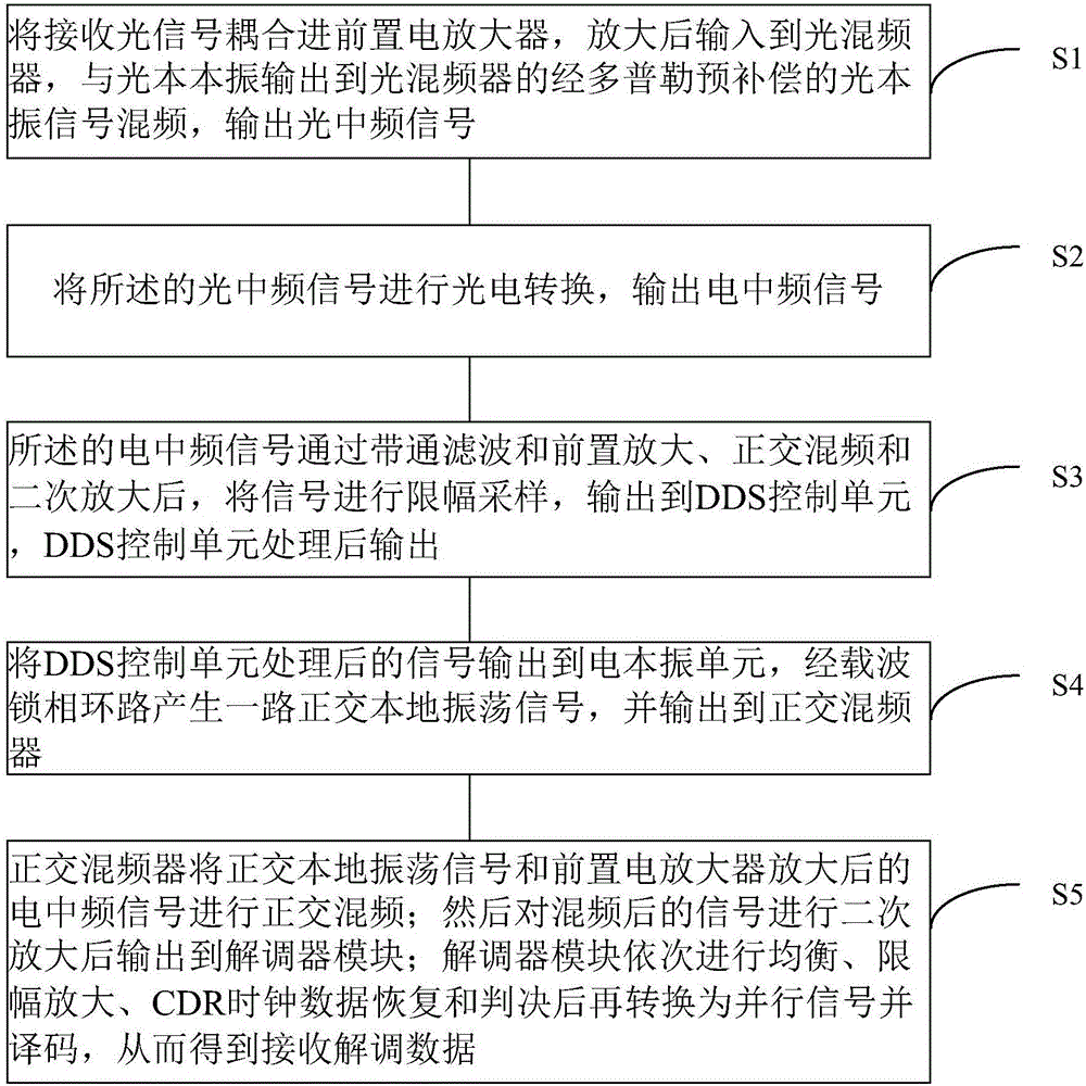
[0045] Such as figure 1 As shown, the digital-analog hybrid heterodyne detection and receiving device provided by the present invention includes: a primary frequency conversion module, a secondary frequency conversion module and a demodulator module; the primary frequency conversion module includes: a pre-optical amplifier 1, an optical frequency mixer device 2, optical balance detector 3, optical local oscillator 4, Doppler compensation unit 5; the secondary frequency conversion module includes: bandpass filter 6, preamplifier 7, quadrature mixer 8, low-pass Filter 9, limiting amplifier 10, electric local oscillator 12, DDS control unit 11. Wherein said quadrature mixer 8, low-pass filter 9, limiting amplifier 10, electric local oscillator 12, DDS control unit 11 form a feedback loop, for eliminating the residual Doppler and tempe...


PUM


Abstract

The invention discloses a digital-analog hybrid heterodyne detection receiving device applicable to space laser communication and a data method. The digital-analog hybrid heterodyne detection receiving device applicable to space laser communication comprises a primary frequency conversion module, a secondary frequency conversion module and a demodulator module, and is characterized in that the primary frequency modulation module comprises a preposed optical amplifier, an optical mixer, a optical balance detector, an optical local oscillator and a Doppler compensation module, Doppler compensation forms voltage signals used for compensating the Doppler frequency shift, and the voltage signals are outputted to the optical local oscillator; the optical local oscillator forms optical local oscillation signals; the optical mixer receives optical signals and the optical local oscillation signals and acquires low-intermediate frequency IF optical signals through mixing; the optical balance detector is connected with an output end of the optical mixer, converts the low-intermediate frequency IF optical signals into electric intermediate-frequency signals and outputs the electric intermediate-frequency signals to the secondary frequency conversion module; and the secondary frequency conversion module performs amplitude-limiting sampling on the electric intermediate-frequency signals and outputs the sampled signals to the demodulator module, and the demodulator module demodulates the sampled signals and outputs demodulated data.

Description

technical field [0001] The invention belongs to the field of space laser communication, and more specifically relates to a receiving device and method for space laser communication. Background technique [0002] At present, space satellite laser communication mainly adopts intensity modulation / direct detection (IM / DD) technology, which has low receiving sensitivity. At the same time, IM / DD technology only uses simple amplitude modulation to transmit information, and does not involve phase and polarization information. It will inevitably reduce the spectrum utilization rate and thus limit its transmission rate. Compared with IM / DD technology, coherent optical communication has sensitivity advantages due to the amplification effect of local oscillator light, and has good frequency selectivity and high spectral efficiency. These characteristics are conducive to the improvement of communication capacity. In addition, in coherent communication, Doppler and channel impairment bet...

Claims


Application Information

Patent Timeline
IPC IPC(8): H04B10/61H04B10/63H04B10/64H04B10/118H04L27/00H04L27/26
CPCH04B10/118H04B10/6164H04B10/6166H04B10/63H04B10/64H04L27/0014H04L27/2695H04L2027/0026
Inventor 张军张传胜冯磊李国通林宝军尚琳毋冬梅
Owner SHANGHAI ENG CENT FOR MICROSATELLITES
Learn More