
A Magneto-Optical Image Enhancement Method Based on Optical Flow Algorithm

An image enhancement and magneto-optical technology, applied in image enhancement, image analysis, image data processing, etc., can solve the problems of large magnetizer, weak anti-interference ability, high energy consumption, etc.

Active Publication Date: 2019-08-20
UNIV OF ELECTRONICS SCI & TECH OF CHINA
View PDF3 Cites 0 Cited by
  • Summary
  • Abstract
  • Description
  • Claims
  • Application Information

AI Technical Summary

Problems solved by technology

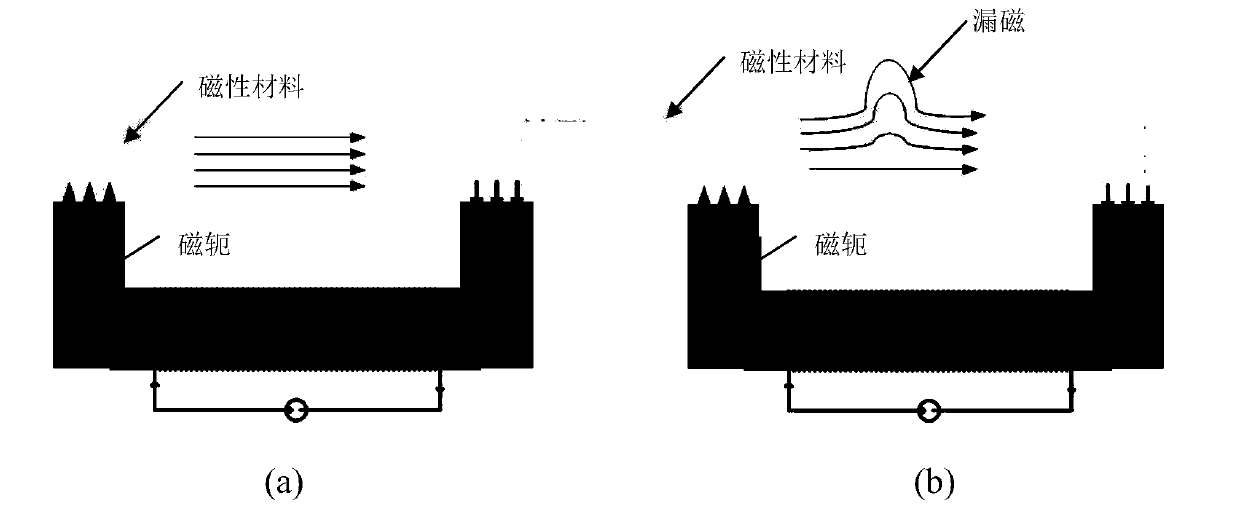
However, due to the DC excitation, not only the magnetizer has a large volume and high energy consumption, but also under a constant magnetization field, the leakage field is constant, and the amount of information obtained is limited, which is not conducive to the extraction of defect features, and the anti-interference ability is weak;

Method used


Image

  • A Magneto-Optical Image Enhancement Method Based on Optical Flow Algorithm
  • A Magneto-Optical Image Enhancement Method Based on Optical Flow Algorithm
  • A Magneto-Optical Image Enhancement Method Based on Optical Flow Algorithm

Examples


Embodiment Construction

[0033] Specific embodiments of the present invention will be described below in conjunction with the accompanying drawings, so that those skilled in the art can better understand the present invention. It should be noted that in the following description, when detailed descriptions of known functions and designs may dilute the main content of the present invention, these descriptions will be omitted here.

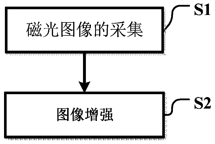
[0034] figure 1 It is a flow chart of the magneto-optical image enhancement method based on the optical flow algorithm of the present invention.

[0035] In this example, if figure 1 As shown, the magneto-optical image enhancement method based on the optical flow algorithm of the present invention includes two major steps, namely:

[0036] Step S1: Acquisition of magneto-optical images

[0037] In the magneto-optical image detection, a sinusoidal AC power supply with a frequency of 0.1 Hz is used as an excitation, and a magnetic material such as a silicon steel sheet is ...


PUM


Abstract

The invention discloses a magneto-optical image enhancement method based on the optical flow algorithm. A low-frequency AC excitation amplifier is used to excite the yoke, and a periodically changing magnetic field is used to obtain image sets under different signal intensities, and the low-frequency signal enables the magnetic lines of force to pass through the yoke. Through the deep area of ​​the measured object, the magneto-optical image can reflect the deepest defect information, which reduces the influence of the skin effect. However, the magneto-optical image obtained in this way has interference noise generated by magnetic domain motion under the action of low-frequency AC signals, which is easily confused with defect information and reduces image detection accuracy. Iterative processing is performed to accumulate the feature points that generate optical flow motion to obtain an enhanced optical flow image. In the enhanced image, the image gradient changes are more obvious, the interference is also greatly reduced, and the defect information is more intuitive.

Description

technical field [0001] The invention belongs to the technical field of nondestructive testing of magnetic materials, and more specifically relates to a magneto-optical image enhancement method based on an optical flow algorithm. Background technique [0002] Non-destructive testing (Non-destructive testing) refers to the use of physical quantity changes caused by abnormal internal structures of materials such as heat, sound, light, electricity, and magnetism on the premise of not damaging or affecting the internal organization of the object to be tested. The change of the physical quantity caused by the change of the material structure is detected, and the change value of the physical quantity is measured to invert the change of the material structure. It is worth noting that the change value of the physical quantity obtained in the experiment may contain a lot of other information, so it is necessary to exclude other external disturbances to make a reliable judgment on the ...

Claims


Application Information

Patent Timeline
Patent Type & Authority Patents(China)
IPC IPC(8): G06T7/00G06T7/269G06T5/50
Inventor 程玉华白利兵黄逸云夏永照殷春王永刚
Owner UNIV OF ELECTRONICS SCI & TECH OF CHINA
Learn More