Positioning method and device for electronic equipment, electronic equipment, and electronic positioning system
A technology of electronic equipment and positioning method, which is applied in the direction of navigation calculation tools, etc., and can solve the problem of low positioning accuracy of electronic equipment
- Summary
- Abstract
- Description
- Claims
- Application Information
AI Technical Summary
Problems solved by technology
Method used
Image

Examples
Embodiment 1
[0031] According to an embodiment of the present invention, an embodiment of a positioning method for an electronic device is provided. It should be noted that the steps shown in the flow charts of the accompanying drawings can be executed in a computer system such as a set of computer-executable instructions, and , although a logical order is shown in the flowcharts, in some cases the steps shown or described may be performed in an order different from that shown or described herein.
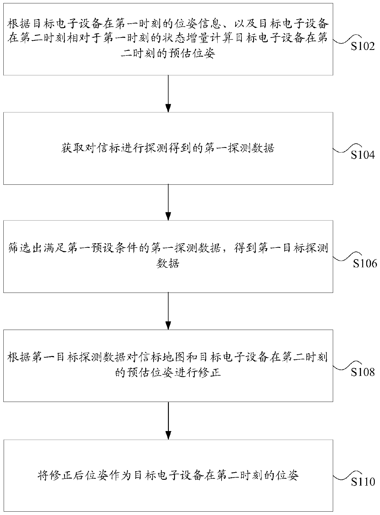
[0032] figure 1 is a flow chart of a positioning method for an electronic device according to an embodiment of the present invention, such as figure 1 As shown, the method includes the following steps:
[0033] Step S102, calculate the estimated pose of the target electronic device at the second moment according to the pose information of the target electronic device at the first moment and the state increment of the target electronic device at the second moment relative to the first moment, whe...
Embodiment 2
[0072] Selectively equipped with state estimation and environment perception sensors on the robot side: at time t, the robot can obtain the state change from time t-1 to time t through state estimation sensors, such as inertial measurement unit, encoder odometer, etc. u t ; It is also possible to obtain environmental observation information z at time t through sensors outside the environmental perception category, such as monocular cameras, stereo cameras, laser radars, millimeter-wave radars, and ultrasonic radars t .
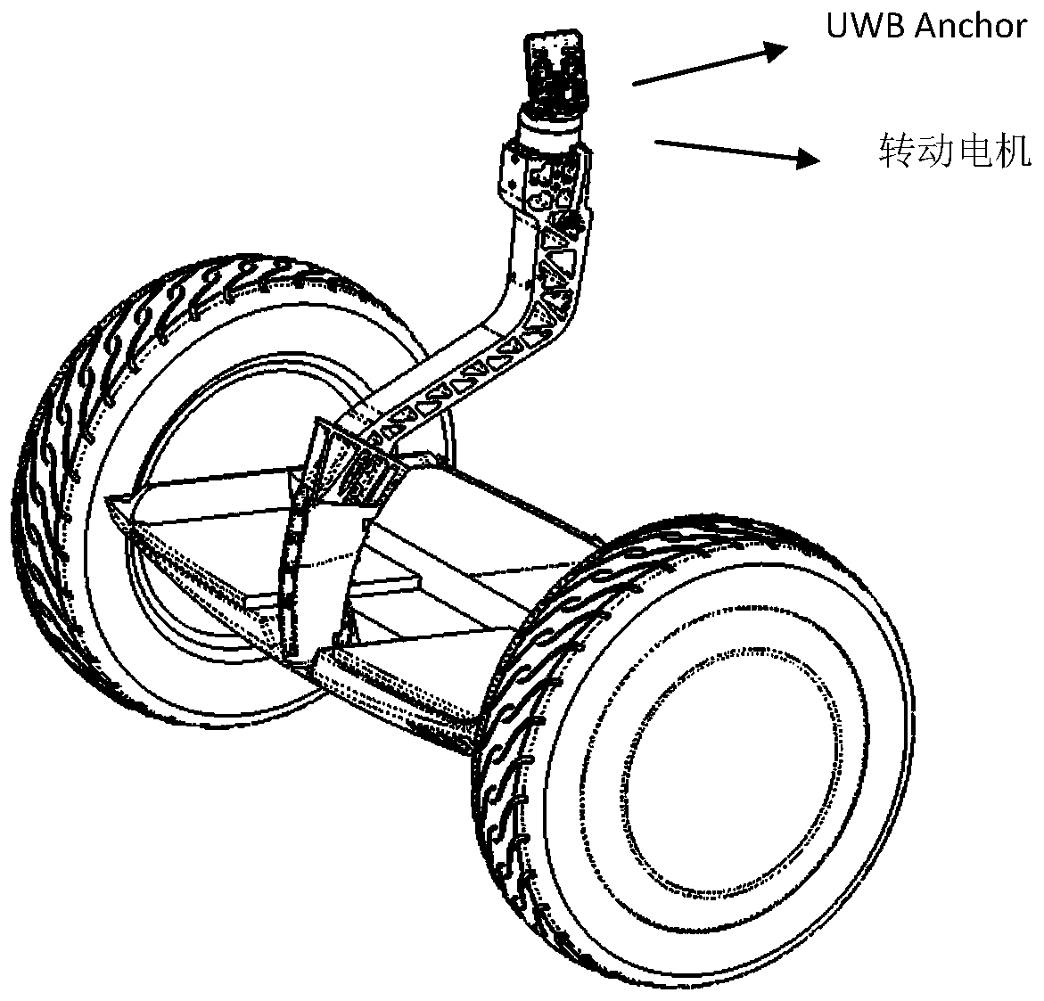
[0073] Configure UWB communication equipment in the SLAM system: In the space environment, place a UWB transmitter beacon (Tag) at a certain distance to ensure that the robot can observe at least one beacon during walking. Install the UWB anchor node (Anchor) on the robot side. The Anchor is equipped with two antennas (or more than two). These two antennas meet the vertical linear polarization conditions. At the same time, the distance between the feed point...
Embodiment 3
[0079] A SLAM system that fuses robot state estimation data (eg, encoder odometry, inertial measurement unit, visual odometry, visual-inertial odometry) and UWB beacon observations. The system estimates robot trajectory and UWB beacon map online.
[0080] Specific steps are as follows:
[0081] 1. Robot pose x 0 Initialization: If the UWB map has not been constructed, the pose of the robot can be initialized with any value; if the UWB map has been constructed, according to the map m y and UWB observation information y 0 Compute the initial pose.
[0082] 2. During the movement of the robot, obtain the state estimation sensor data u t (For example: encoder odometer, visual inertial odometer, etc., from time t-1 to time t), update the robot pose assumption according to the robot motion model
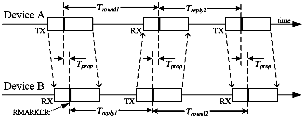
[0083] 3. Obtain UWB observation data For example: get the distance d of the UWB beacon relative to the robot through TWR; get the distance d and the included angle θ of the UWB b...
PUM
 Abstract
Description
Claims
Application Information
 - R&D
- Intellectual Property
- Life Sciences
- Materials
- Tech Scout
- Unparalleled Data Quality
- Higher Quality Content
- 60% Fewer Hallucinations
Browse by: Latest US Patents, China's latest patents, Technical Efficacy Thesaurus, Application Domain, Technology Topic, Popular Technical Reports.
© 2025 PatSnap. All rights reserved.Legal|Privacy policy|Modern Slavery Act Transparency Statement|Sitemap|About US| Contact US: help@patsnap.com