A multi-country plug converter
A converter and plug technology, applied in coupling devices, electrical components, protective grounding/shielding devices of connecting parts, etc., can solve the problems of inability to use, inconvenient to carry, large in size, etc. carry effect
- Summary
- Abstract
- Description
- Claims
- Application Information
AI Technical Summary
Problems solved by technology
Method used
Image
Examples
Embodiment 1
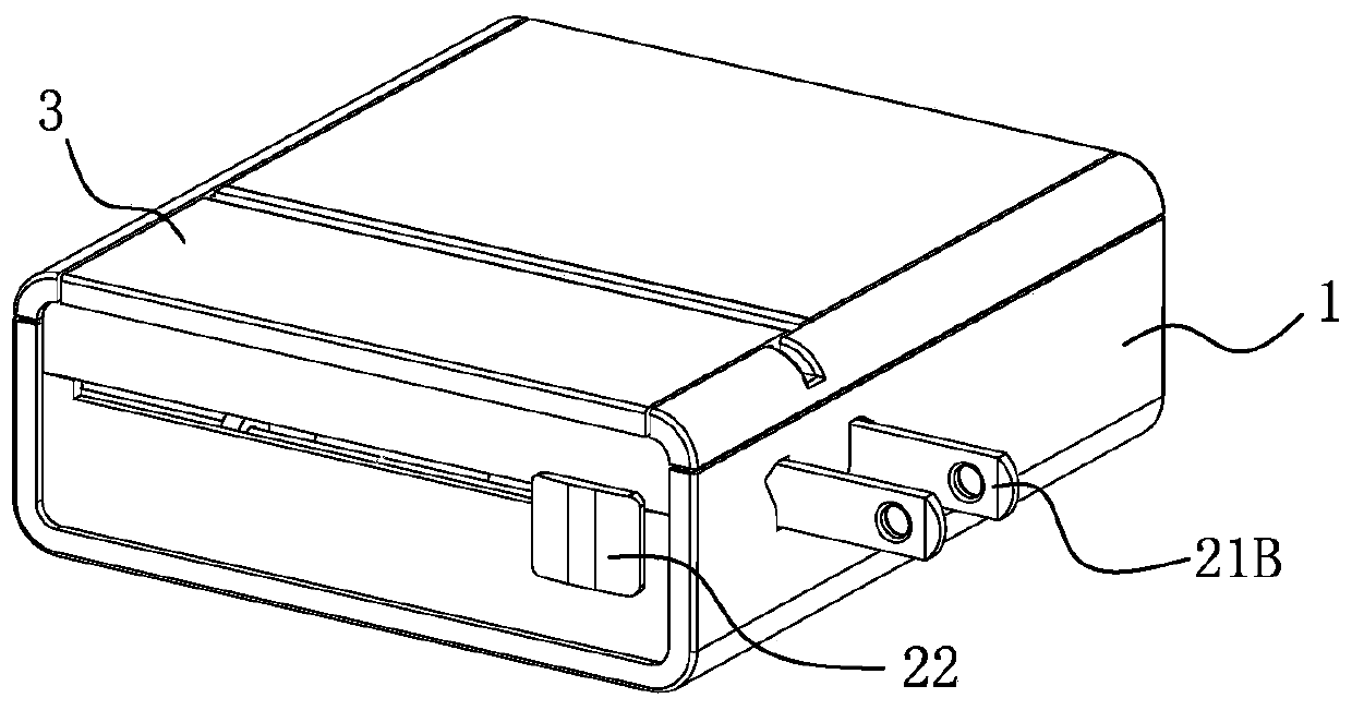
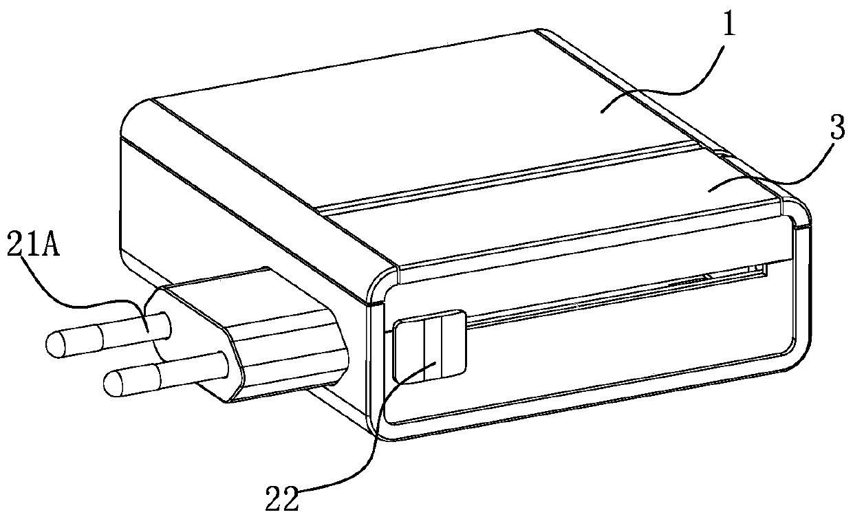
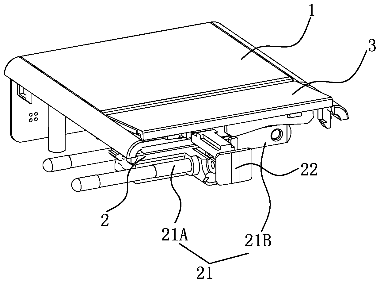
[0034] See Figure 1-4B As shown, a multi-country plug converter has a socket body 1. The socket body 1 is fastened by the front and rear shells or fixed and combined by screws to form a rectangular socket body 1. A cavity is formed inside the socket body 1; A set of plug sliders 2 are installed in the cavity of the socket body 1. Conductive pins 21 of different specifications are respectively installed on the left and right sides of the plug slider 2. The plug slider 2 is connected with a push button 22, and the push button 22 is exposed on the socket body. 1. Drive the plug slider 2 to move back and forth in the socket body 1 through the push button 22, so as to drive the conductive pin 21 to push out the left and right sides of the socket body 1, and combine with the conductive pin protruding out of the socket body 1 to form a grounded Wire plug.
[0035] Specifically, after the combination of the front and rear shells, there is a groove inside the socket body 1, and the g...
Embodiment 2
[0047] See Figure 8-10A As shown, the difference between the second embodiment and the first embodiment is that one end of the plug ground pin 30 is pivotally connected to the inner side of the flip cover 3 through a rotating shaft structure, so that the plug ground pin 30 can be vertically flipped out. Lift the cover 3 outside. The left and right sides of the plug ground pin 30 are formed with pivot shafts 303, and the flip cover 3 is formed with a pivot seat 304 corresponding to the pivot shaft 303. The pivot shaft 303 cooperates with the pivot seat 304 to pivotally connect the plug ground pin 30. The flip cover 3 can be turned over vertically; the flip cover is provided with a positioning structure for the positioning of the plug ground pins after they are turned out or turned into the flip cover. The positioning structure is: the side of the plug ground pin 30 is set There is a buckle opening 305, and the flip cover 3 is provided with a clasp 306 corresponding to the buc...
Embodiment 3
[0051] See Figure 11 As shown, the difference between the present embodiment and the first embodiment is that a card slot 31 is provided on the side where the ground pin 30 of the plug is bonded to the flip cover 3, and the opening width of the upper end of the card slot 31 is smaller than the width of the bottom surface of the card slot 31. The inner side of flip cover 3 is provided with tenon 32 and can be slid into slot 31; It can extend out of the flip cover 3 along the inner side of the flip cover 3. In this embodiment, the plug ground pin 30 can extend out of the flip cover 3 by moving to the left. Or a separate limiting structure to prevent the plug ground pin 30 from detaching from the flip cover 3 .
[0052] In this embodiment, a pivot hole is formed at the end where the flip cover 3 is pivotally connected to the socket body 1 , and a pivot shaft is formed on the socket body 1 correspondingly to complete the rotational connection between the two.
PUM
 Abstract
Description
Claims
Application Information
 - Generate Ideas
- Intellectual Property
- Life Sciences
- Materials
- Tech Scout
- Unparalleled Data Quality
- Higher Quality Content
- 60% Fewer Hallucinations
Browse by: Latest US Patents, China's latest patents, Technical Efficacy Thesaurus, Application Domain, Technology Topic, Popular Technical Reports.
© 2025 PatSnap. All rights reserved.Legal|Privacy policy|Modern Slavery Act Transparency Statement|Sitemap|About US| Contact US: help@patsnap.com


