Steel wire rope detour splicing structure and method of precast concrete wall panel components

A technology of prefabricated concrete and prefabricated components, which is applied to building components, walls, building structures, etc., can solve the problems of low grouting sleeve construction efficiency, difficult transportation and hoisting operations, and large on-site wet workload. and hoisting operations, reducing the risk of cracking and reducing the amount of work

Active Publication Date: 2019-05-10
CHINA UNIV OF MINING & TECH
View PDF9 Cites 0 Cited by
  • Summary
  • Abstract
  • Description
  • Claims
  • Application Information

AI Technical Summary

Problems solved by technology

[0006] Purpose of the invention: In order to overcome the deficiencies in the prior art, the present invention provides a structure and method for splicing wire ropes of prefabricated concrete wall panels to solve the problems caused by the multi-sided reinforcement of prefabricated components in the splicing methods of existing wall panels. Low production efficiency, difficult transportation and hoisting operations, large wet workload on site, low construction efficiency of grouting sleeve connection, etc.

Method used


Image

  • Steel wire rope detour splicing structure and method of precast concrete wall panel components
  • Steel wire rope detour splicing structure and method of precast concrete wall panel components
  • Steel wire rope detour splicing structure and method of precast concrete wall panel components

Examples


Embodiment 1

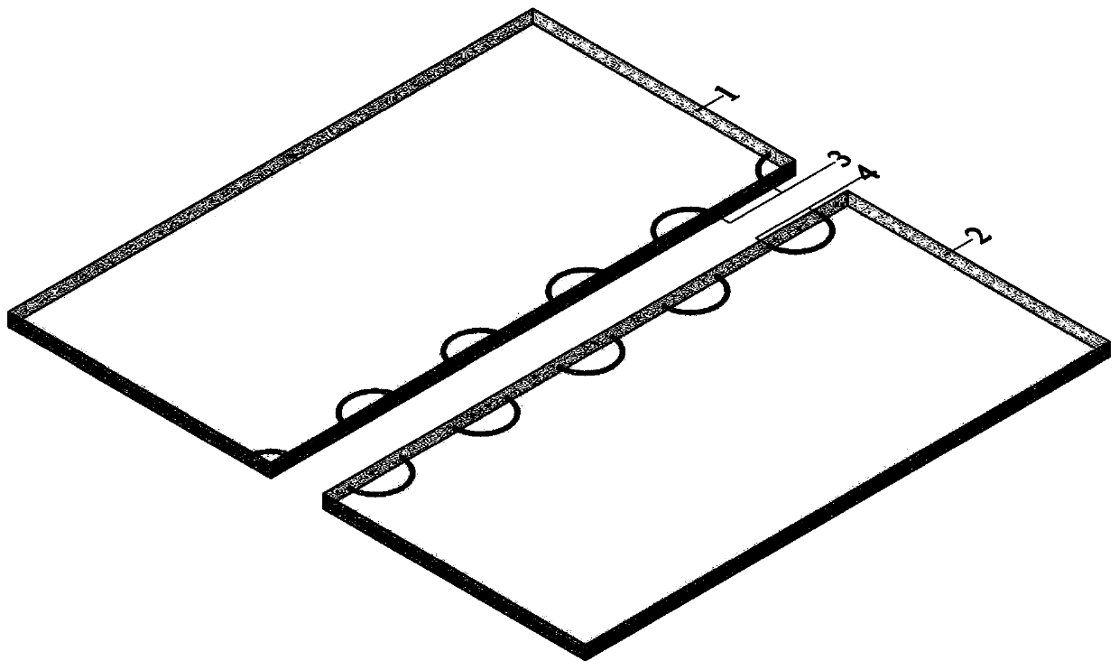
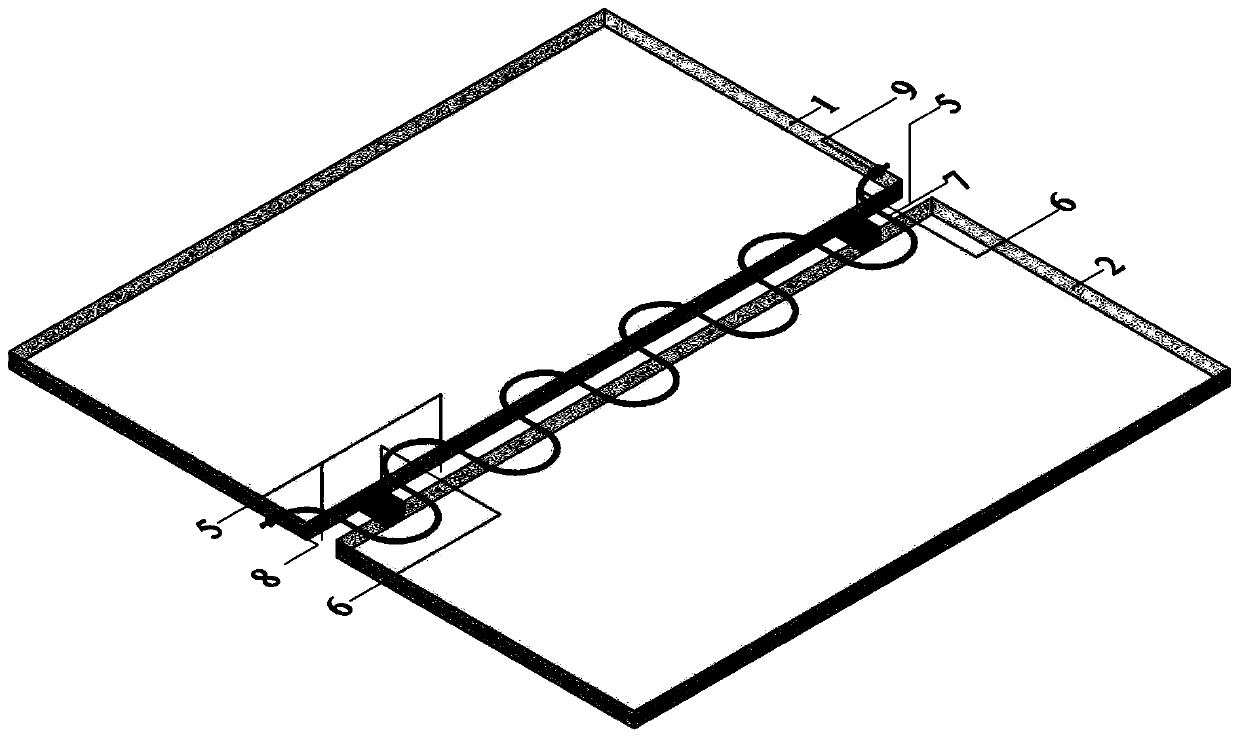
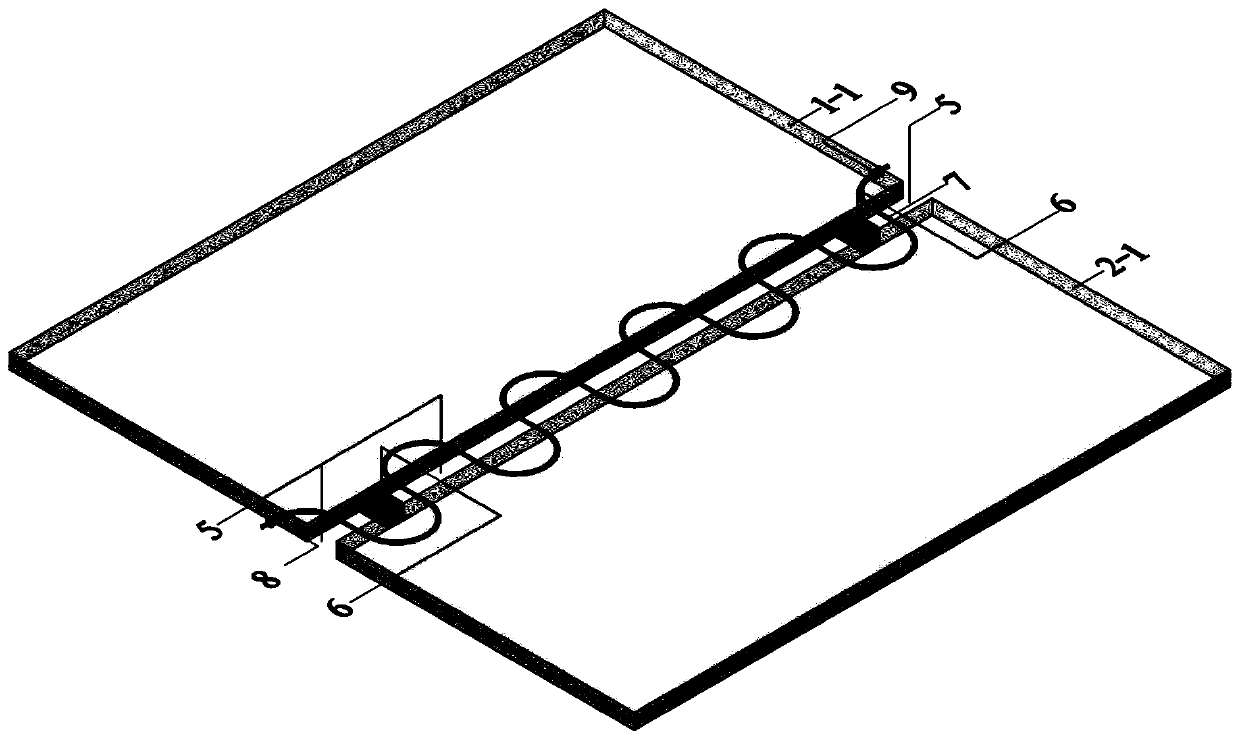
[0032] Such as image 3 As shown, it is a slab-slab splicing structure within a span, and the splicing objects are prefabricated floor 1-1 spliced ​​within a span and prefabricated floor 2 spliced ​​within a span 2-1, prefabricated floor 1-1 spliced ​​within a span and prefabricated floor spliced ​​within a span The floor plate two 2-1 is respectively provided with a plurality of smooth and curved first rope-through holes 3 and second rope-through holes 4 inwardly from the splicing edge (see details). figure 1 ). Since the slabs are spliced ​​across the span, the first rope-threading hole 3 and the second rope-threading hole 4 are respectively located below the midplane of the spliced ​​prefabricated floor 1-1 within the span and the prefabricated floor 2 2-1 spliced ​​across the span. This ensures that the steel wire rope 7 inserted in the later stage can effectively resist the bending moment action of the splicing part.

[0033] When splicing and assembling, after the pref...

Embodiment 2

[0035] Such as Figure 4 As shown, it is a splicing structure at the slab support, and the splicing objects are splicing prefabricated floor 1-2 at the support and prefabricated floor 2 2-2 at the support, splicing prefabricated floor 1-2 and Splicing the prefabricated floor 2 2-2 at the support is respectively provided with several smooth curve-shaped first stringing holes 3 and second stringing holes 4 inwardly from the splicing edge (see details). figure 1 ). Due to the splicing connection at the slab support, the first stringing hole 3 and the second stringing hole 4 are above the middle planes of the spliced ​​prefabricated floor 1-2 at the support and the spliced ​​prefabricated floor 2 2-2 at the support respectively position, so as to ensure that the steel wire rope 7 inserted in the later stage can effectively resist the bending moment action on the splicing position.

[0036]When splicing and assembling, after splicing prefabricated floor 1-2 at the support and spl...

Embodiment 3

[0038] Such as Figure 5 As shown, it is a wall vertical splicing structure, and the splicing objects are vertically splicing prefabricated wall panels 1-3 and vertically splicing prefabricated wall panels 2-3, vertically splicing prefabricated wall panels 1-3 and vertical To the splicing prefabricated wall panel two 2-3, be respectively provided with the first threading hole 3 of several smooth curves and the second threading hole 4 (see details) inwardly from the splicing edge figure 1 ). Preferably, the first stringing hole 3 and the second stringing hole 4 are respectively located at the midplanes of the vertically spliced ​​prefabricated wall panel one 1-3 and the vertically spliced ​​prefabricated wall panel two 2-3.

[0039] When splicing and assembling, after the vertical splicing prefabricated wall panel 1-3 and the vertical splicing prefabricated wall panel 2 2-3 are in place, leave a post-cast joint 5 between them and place a limit pad 6 in the joint, Then the wir...


PUM


Abstract

The invention discloses a steel rope bypass splicing structure and method of a prefabricated concrete wall panel component. Splicing objects are a first prefabricated component and a second prefabricated component that are of a wall panel shape; the first / second prefabricated component is inwardly provided with a group of smooth curve first / second rope holes in a manner of being perpendicular to a splicing surface; the first rope holes and the second rope holes intersect transversely and are consistent vertically relative to the splicing objects, and the hole mouths are tangent; and the steel rope penetrates through the first rope holes and the second rope holes in an intersecting and then bypassing manner so as to connect the first prefabricated component with the second prefabricated component. Reinforcing bars protrude out of four corners of the existing wall panel splicing prefabricated component, causing problems that an edge model of the prefabricated component is complex, the production efficiency is low, and transport and hoisting operations are difficult; laminated pouring of the existing prefabricated splicing floor slab structure causes much wet work on the site, and decoration layer construction cannot be finished in a prefabrication factory; and grouting sleeves of the existing prefabricated splicing wall panel structure are connected, resulting in poor construction quality and low efficiency. Through adoption of the steel rope bypass splicing structure and method of the prefabricated concrete wall panel component, the above problems are solved.

Description

technical field [0001] The invention relates to a splicing connection structure and method of prefabricated concrete wall panel components, belonging to construction engineering technology. Background technique [0002] In recent years, with the continuous improvement of people's requirements for living conditions and living environment, the construction industry has developed rapidly. However, the development of the construction industry has caused serious resource consumption and environmental pollution, forcing people to seek a new way out of the construction industry. At present, the industrialization of buildings characterized by prefabricated buildings is one of the key ways to achieve low-carbon and sustainable development in the construction industry. [0003] In prefabricated buildings, the connection mode between structural components has a crucial influence on the efficiency of prefabricated and assembled construction and the mechanical properties of service. Am...

Claims


Application Information

Patent Timeline
Patent Type & Authority Patents(China)
IPC IPC(8): E04B2/72E04B1/61
CPCE04B1/612E04B2/721
Inventor 李富民刘旭雷斌赵婕
Owner CHINA UNIV OF MINING & TECH
Why Eureka
Try Eureka