
Brake-by-wire device based on assistance of direct-current motor

A technology of DC motor and brake-by-wire, which is applied in the direction of brake transmission, brake, transportation and packaging, etc. It can solve the problems of unfavorable high integration requirements, many parts of the brake device, and low integration, and achieve failure Good stability, high integration, and volume-saving effect

Inactive Publication Date: 2017-09-05
JILIN UNIV
View PDF4 Cites 11 Cited by
  • Summary
  • Abstract
  • Description
  • Claims
  • Application Information

AI Technical Summary

Problems solved by technology

However, in today's motor-assisted hydraulic brake-by-wire systems, the brake device itself generally has many parts and is arranged in a scattered manner. Therefore, the current brake device has a large volume and low integration. The layout occupies a large area, which is not conducive to the high integration requirements of the emerging electric vehicle industry and many other defects

Method used


Image

  • Brake-by-wire device based on assistance of direct-current motor
  • Brake-by-wire device based on assistance of direct-current motor
  • Brake-by-wire device based on assistance of direct-current motor

Examples


specific Embodiment approach

[0054] In order to further illustrate the technical solution of the present invention, in conjunction with the accompanying drawings, the specific implementation of the present invention is as follows:

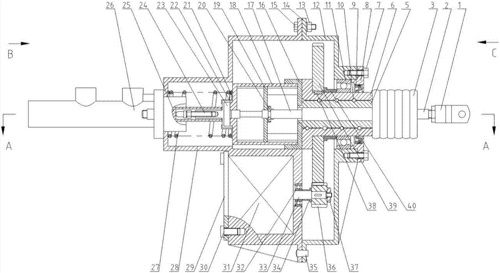
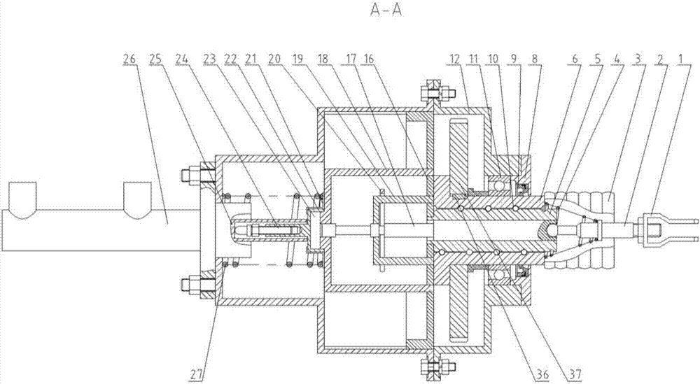
[0055] Such as figure 1 As shown, the present invention provides a brake-by-wire device based on a DC motor, the brake-by-wire device is installed between the brake pedal and the brake master cylinder, and is mainly composed of a U-shaped joint 1, a valve stem 2, a valve Rod return spring 4, roller screw screw 5, ball screw nut 6, rear housing 12, valve body seat 16, pedal lever 17, valve body 18, pedal support 19, locking plate 20, master cylinder push rod Seat 22, rubber buffer block 23, master cylinder push rod 24, master cylinder piston rod 25, brake master cylinder 26, master cylinder push rod return spring 27, front housing 28, DC motor 31, pinion 36 and bull gear 39 compositions.

[0056] Such as figure 1 with Figure 5 As shown, the rear housing 12 and the front ho...


PUM


Abstract

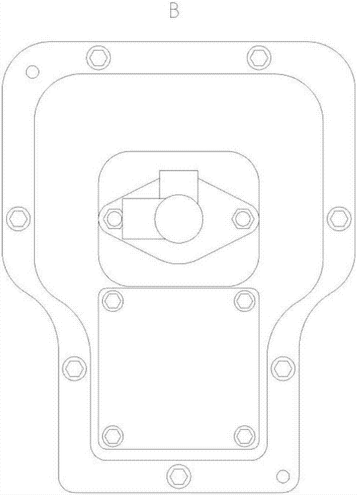
The invention discloses a brake-by-wire device based on the assistance of a direct-current motor. In the device, a ball screw pair is mounted in the rear part of the interior of a shell, a valve body seat is slidably connected into the shell at the front end of the ball screw pair along an axial direction, both a valve body and a pedal support are mounted on the front end surface of the valve body seat, moreover, the pedal support is slidably connected into the valve body along the axial direction, a pedal rod sequentially passes through a ball screw rod, the valve body seat, the pedal support and the valve body along the axial direction front back to front, the pedal rod and the pedal support are fastened and locked together by a locking plate, a valve rod assembly is connected to the rear end of the pedal rod, a brake cylinder assembly is connected to the front end of the pedal rod along the axial direction, a direct-current motor is mounted under the outside of the shell, a small gear is mounted on a motor output shaft, a big gear is mounted on the outside of a ball screw nut, and the big gear is engaged with the small gear. Since the structure of the brake-by-wire device is reasonably optimized by the invention, the size of the brake-by-wire device is small, the integration degree is high, and thereby the volume occupied by a brake system in overall arrangement can be effectively reduced.

Description

technical field [0001] The invention belongs to the technical field of automobile brake systems. More specifically, it relates to a DC motor-assisted brake-by-wire device. Background technique [0002] The braking system of a traditional car usually uses a vacuum booster device, which has the disadvantages of large volume, complex structure, low integration, complex parts, and great dependence on the engine. At present, the use of vacuum booster systems has been canceled on most cars . With the overall rapid development of today's automobile industry, people put forward high requirements for the integration and light weight of automobiles, and the demand for highly integrated automobile braking devices is gradually increasing. In order to meet the pursuit and development needs of a braking system with stable performance and high integration in related technical fields, people have gradually begun to research and explore brake-by-wire systems. [0003] The brake-by-wire sy...

Claims


Application Information

Patent Timeline
Patent Type & Authority Applications(China)
IPC IPC(8): B60T13/74
CPCB60T13/745
Inventor 李静刘鹏王晨王洁新
Owner JILIN UNIV
Learn More