
Oil supply device and lopper saw

A technology of oil supply device and high branch saw, which is applied in the directions of engine components, engine lubrication, mechanical equipment, etc., can solve the problems of bulky oil supply device, affecting the operation of implementing tools, etc., achieves small size, avoids the influence of angle, structure Simple and compact effect

Inactive Publication Date: 2017-09-01
ZHEJIANG TITAN MACHINERY
View PDF8 Cites 7 Cited by
  • Summary
  • Abstract
  • Description
  • Claims
  • Application Information

AI Technical Summary

Problems solved by technology

[0005] The purpose of the present invention is to provide an oil supply device and a high-branch saw to solve the technical problem that the oil supply device in the prior art is bulky and affects the implementation of tool operation

Method used


Image

  • Oil supply device and lopper saw
  • Oil supply device and lopper saw
  • Oil supply device and lopper saw

Examples


Embodiment 1

[0035] This embodiment provides an oil supply device, such as Figure 6-Figure 9As shown, it includes an oil pump casing 1 and an oil pump plunger 2. The oil pump casing 1 is provided with a housing chamber for accommodating the oil pump plunger 2. The oil pump plunger 2 includes a driving part 21, a stroke limiting part 22 and an oil delivery part in sequence along its axial direction. Part 23, the oil delivery part 23 and the stroke limiting part 22 are all movably inserted in the accommodation chamber, and the side wall of the oil pump plunger 2 is sealed with the inner wall of the oil pump casing 1; the driving part 21 is connected with a driving device, and the driving device is used for The driving part 21 is driven to rotate in the circumferential direction; the oil pump casing 1 is provided with a stroke limiting device, which is used to limit the movement stroke of the stroke limiting part 22 along the axial direction of the oil pump plunger 2; the side wall of the oil...

Embodiment 2

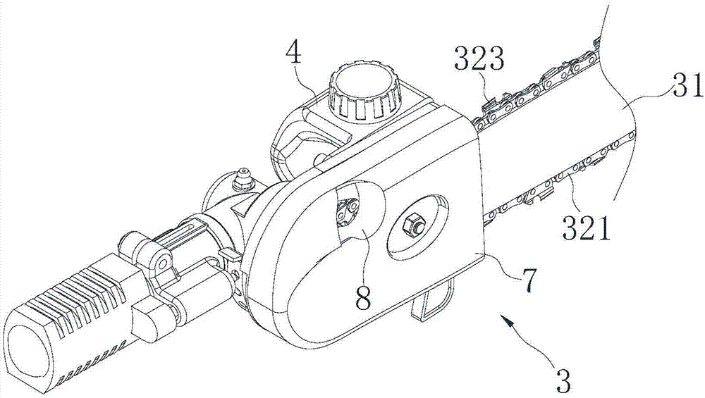
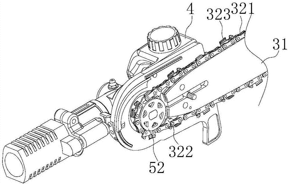
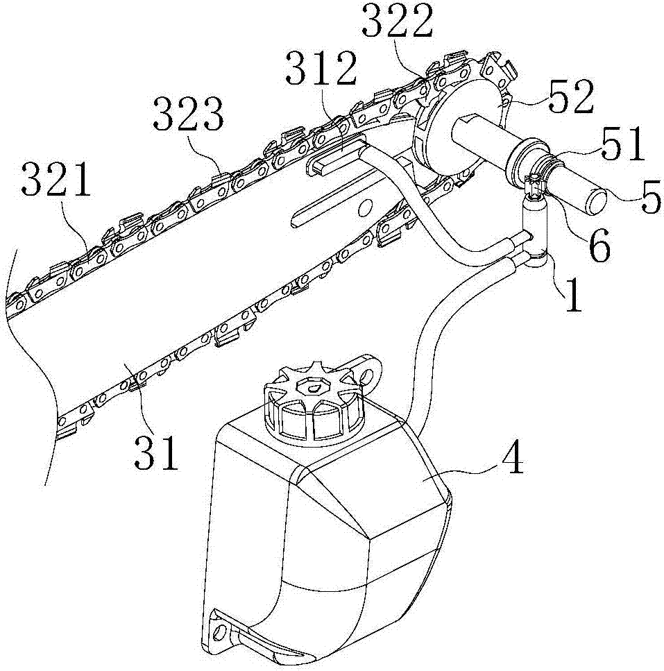
[0041] This embodiment also provides a high branch saw, such as Figure 1-Figure 3 , Figure 5 As shown, the saw head 3 and the oil supply device described in Embodiment 1 are included. The saw head 3 includes a guide plate 31, and the outer circumference of the guide plate 31 is provided with a guide groove 311 inwardly, and a chain 32 for cutting branches is clamped in the guide groove 311. , the guide groove 311 communicates with the oil outlet 12 of the oil supply device; the oil inlet 11 of the oil supply device communicates with the oil pot 4 through a pipeline.

[0042] The high-branch saw provided in this embodiment includes a saw head 3 for implementing tools. The saw head 3 includes a chain 32 for cutting branches, and the chain 32 is clamped on the outer periphery of the guide plate 31 . When the saw head 3 works, the chain 32 rotates around the guide plate 31 at high speed to cut the branches. The lubricating oil in the oil pot 4 enters the oil supply device from ...


PUM


Abstract

The invention provides an oil supply device and a lopper saw and relates to the technical field of garden tools. The oil supply device comprises an oil pump shell and an oil pump plunger; a stroke limit part and an oil delivery part of the oil pump plunger are spliced into an accommodating cavity of the oil pump shell; and a chamber for accommodating lubricating oil is formed between an oil accommodating tank formed in the oil delivery part of the oil pump plunger and the inner wall of the oil pump shell. The lopper saw comprises a saw head and the oil supply device; the saw head comprises a guide plate; a guide slot is inwards formed in the periphery of the guide plate; a cutting chain is clamped in the guide slot; an oil storage tank connected with the guide slot is arranged on the guide plate; and the oil storage tank communicates with an oil outlet of the oil supply device by a pipeline. The oil pump plunger does reciprocating and circulating movement in the oil pump shell under the driving of a driving device and the stroke limit of a stroke limit device so as to supply oil for an external device; and the oil supply device is simple and compact in structure, relatively small in size and capable of reducing the operation of implementing tools as much as possible.

Description

technical field [0001] The invention relates to the technical field of garden tools, in particular to an oil supply device and a high branch saw. Background technique [0002] With the rapid development of modern society, environmental issues are becoming more and more important in people's minds, and people are becoming more and more aware of the importance of greening to our living environment. In the greening process, we need to pruning the garden branches. When the branches that need to be felled or pruned are high, we generally use high-branch saws. High-branch saws refer to high-position branch pruning saws, also known as lawn mowers and motorized sickles. , is one of the commonly used garden machines for pruning trees in landscaping, and the high branch saw is widely used for its advantages such as high efficiency and labor saving. [0003] The high-speed rotating chain on the saw head of the high-branch saw drives the blades on the chain to cut the branches. During ...

Claims


Application Information

Patent Timeline
Patent Type & Authority Applications(China)
IPC IPC(8): F16N7/38
CPCF16N7/38
Inventor 郭晓峰
Owner ZHEJIANG TITAN MACHINERY
Learn More