
Wire frame pole and integrally assembled wire frame pole axial force testing method

A grid rod and assembled technology, which is applied to truss structures, force/torque/work measuring instruments, measuring devices, etc., can solve the problems of large workload, complex force transmission mode, huge workload, etc. Force, huge economic benefits, the effect of simplifying the measurement process

Inactive Publication Date: 2017-09-01
LIAONING TECHNICAL UNIVERSITY
View PDF5 Cites 4 Cited by
  • Summary
  • Abstract
  • Description
  • Claims
  • Application Information

AI Technical Summary

Problems solved by technology

In the past, the method of pre-embedded strain gauges usually used in structural health monitoring has a serious defect of insufficient service life of the strain gauges, and the method of pasting the strain gauges on site will not only bring a huge workload to the detection, but also inevitably bring a lot of problems. High-altitude work has a high risk factor
The method of measuring the axial force of the member by the frequency method is due to the complex force transmission mode of the bolt ball joint, and the frequency change caused by the influence of the surrounding members on the bending and elastic constraints cannot be ignored, and its accuracy needs to be further improved
The method of using the magnetic flux method to measure the force on the rod often requires on-site winding of the Harvard sensor, which is a huge workload and cannot be reused at a high cost.

Method used


Image

  • Wire frame pole and integrally assembled wire frame pole axial force testing method
  • Wire frame pole and integrally assembled wire frame pole axial force testing method
  • Wire frame pole and integrally assembled wire frame pole axial force testing method

Examples


Embodiment Construction

[0021] The specific embodiments of the present invention will be described in detail below in conjunction with the accompanying drawings.

[0022] A grid rod, such as figure 1 As shown, it includes three structural units, which are the first grid rod round steel pipe 1, the second grid rod round steel pipe 2 and the axial force sensor 3. The three structural units form a whole that participates in the force;

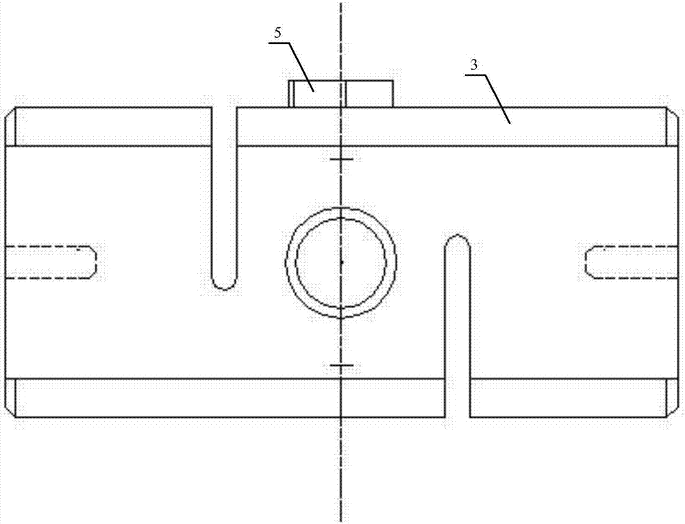
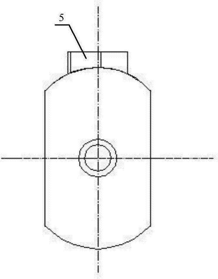
[0023] One end of the first grid rod round steel pipe 1 is connected to one end of the axial force sensor 3 through a high-strength bolt 4, and the other end of the axial force sensor 3 is connected to one end of the second grid rod round steel pipe 2. The data acquisition device connection port 5 of the axial force sensor 3 is connected to the input end of the data acquisition device.

[0024] In this embodiment, the axial force sensor 3 adopts an S-shaped column type axial force sensor, such as figure 2 and image 3 shown.

[0025] The S-column axial force sensor ...


PUM


Abstract

The invention provides a wire frame pole and an integrally assembled wire frame pole axial force testing method. The wire frame pole comprises three structural units respectively including a first wire frame pole circular steel pipe (1), a second wire frame pole circular steel pipe (2) and an axial force sensor (3), and the three structural units form an integral body participating in stress; the testing method comprises the following steps: according to the stress situations of the integrally assembled wire frame pole, selecting a wire frame pole needing axial force testing, selecting a corresponding range of axial force sensor according to the stress of the wire frame pole, and calibrating and zeroing; assembling the first wire frame pole circular steel pipe, the second wire frame pole circular steel pipe and the axial force sensor through high-strength bolts, and integrally assembling; constructing by adopting the integrally assembled wire frame pole, and acquiring signals output by the axial force sensor through data acquisition equipment, thus completing the axial force stress analysis of the integrally assembled wire frame pole. The measurement flow can be greatly simplified, the workload can be reduced, and tremendous economic benefits can be achieved.

Description

technical field [0001] The invention belongs to the technical field of axial force testing of grid structure rods, and in particular relates to a grid rod and an axial force testing method of an integrally assembled grid rod. Background technique [0002] With the rapid development of my country's economy, grid structure is widely used in public buildings or industrial plants with large investment scale and strong social influence due to its series of significant advantages compared with traditional concrete structures. For some buildings that have been put into use, there may be deviations between the actual force of the structure and the theoretical design due to defects in the design or construction stage; and the aging of the building structure with the increase in service life A series of problems such as structural strength reduction and stiffness degradation. If these problems cannot be discovered and solved in time during the use stage, once the building is damaged,...

Claims


Application Information

Patent Timeline
IPC IPC(8): E04C3/04G01L5/00
CPCE04C3/04G01L5/00
Inventor 殷志祥宁志扬梁艺洪淼
Owner LIAONING TECHNICAL UNIVERSITY
Learn More