Rotating replacement device
A technology of rotating body and rotating shaft, which is applied in the direction of tool changing device, positioning device, resistance welding equipment, etc. It can solve problems such as damage, deformation of gun body and welding torch components, and achieve the effect of avoiding deformation or damage
- Summary
- Abstract
- Description
- Claims
- Application Information
AI Technical Summary
Problems solved by technology
Method used
Image
Examples
no. 1 approach
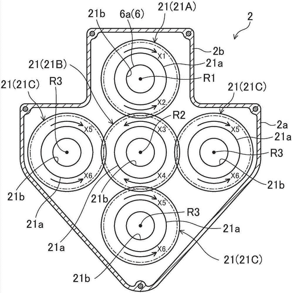
[0080] figure 1 The rotation changing device 1 according to the first embodiment of the present invention is shown. This rotary replacement device 1 is used to automatically replace metal nozzles 11 and contact tips 12, which are welding torch components of a welding torch 10 used for welding steel plates or the like by arc welding (refer to Figure 8 to Figure 21 ).
[0081] The welding gun 10 has a cylindrical gun body 10a, and the cylindrical nozzle 11 is detachably connected to the tip of the gun body 10a by screwing.
[0082] The tip side of the nozzle 11 has a tapered shape whose diameter gradually decreases as it approaches the tip opening. The engaged portion 11a.
[0083] That is, the engaged portion 11a is configured such that a plurality of tooth portions and tooth groove portions extending along the central axis of the nozzle 11 are alternately provided around the central axis.
[0084] The top end of the gun body 10 a is screwed with the thin rod-shaped copper...
no. 2 approach
[0205] Figure 22 to Figure 29 The detaching unit 4 of the rotation changing device 1 according to the second embodiment of the present invention is shown. In this second embodiment, only a part of the structure of the disassembly unit 4 and the discarding method of the used contact tip 12 removed from the gun body 10a are different from the first embodiment, and the other aspects are the same as the first embodiment , so only the parts different from the first embodiment will be described in detail below.
[0206]The first grooved groove 41e is not formed in the thick portion 41b of the first rotating body 41 in the second embodiment like in the first embodiment.
[0207] In addition, the stopper member 41d is not fitted into the outer peripheral surface near the lower end of the first rotating body 41 like in the first embodiment.
[0208] Furthermore, a socket-shaped contact portion 41f is formed on the upper opening periphery of the through hole 41a of the first rotating...
no. 3 approach
[0249] Figure 30 to Figure 36 The detaching unit 4 of the rotation changing device 1 according to the third embodiment of the present invention is shown. In this third embodiment, only a part of the structure of the disassembly unit 4 and the discarding method of the used contact tip 12 removed from the gun body 10a are different from the second embodiment, and the other aspects are the same as the second embodiment , so only the parts different from the second embodiment will be described in detail below.
[0250] Such as Figure 30 and Figure 31 As shown, an annular wall portion 41g that bulges outward and extends upward is provided on the upper end outer peripheral edge portion of the thick wall portion 41b of the first rotating body 41 of the third embodiment, and the annular wall portion 41g On the inner peripheral surface of the upper half of the upper part, four concave portions 41h that are concave radially outward and extend up and down are formed at equal interv...
PUM
 Abstract
Description
Claims
Application Information
 - R&D
- Intellectual Property
- Life Sciences
- Materials
- Tech Scout
- Unparalleled Data Quality
- Higher Quality Content
- 60% Fewer Hallucinations
Browse by: Latest US Patents, China's latest patents, Technical Efficacy Thesaurus, Application Domain, Technology Topic, Popular Technical Reports.
© 2025 PatSnap. All rights reserved.Legal|Privacy policy|Modern Slavery Act Transparency Statement|Sitemap|About US| Contact US: help@patsnap.com


