
Terminal used fingerprint identification method, device and the terminal

A fingerprint identification and terminal technology, applied in the field of image processing, can solve problems such as affecting fingerprint image collection and reducing fingerprint identification accuracy.

Active Publication Date: 2017-08-29
添津人工智能通用应用系统(天津)有限公司
View PDF6 Cites 7 Cited by
  • Summary
  • Abstract
  • Description
  • Claims
  • Application Information

AI Technical Summary

Problems solved by technology

However, in this method of using the terminal touch panel to perform fingerprint recognition operations, as the area of ​​the touch panel (ie, the fingerprint recognition area) increases, there are more and more factors affecting the accuracy of fingerprint recognition. When there are stains, some stains will affect the collection of fingerprint images, thereby reducing the accuracy of fingerprint recognition

Method used


Image

  • Terminal used fingerprint identification method, device and the terminal
  • Terminal used fingerprint identification method, device and the terminal
  • Terminal used fingerprint identification method, device and the terminal

Examples


no. 1 example

[0080] The first embodiment of the present invention proposes a fingerprint identification method using a terminal, which can be applied to a terminal with a fingerprint identification function.

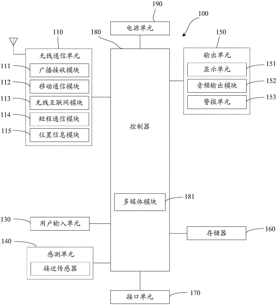
[0081] Here, the terminal described above may be a fixed terminal with a display screen, or a mobile terminal with a display screen.

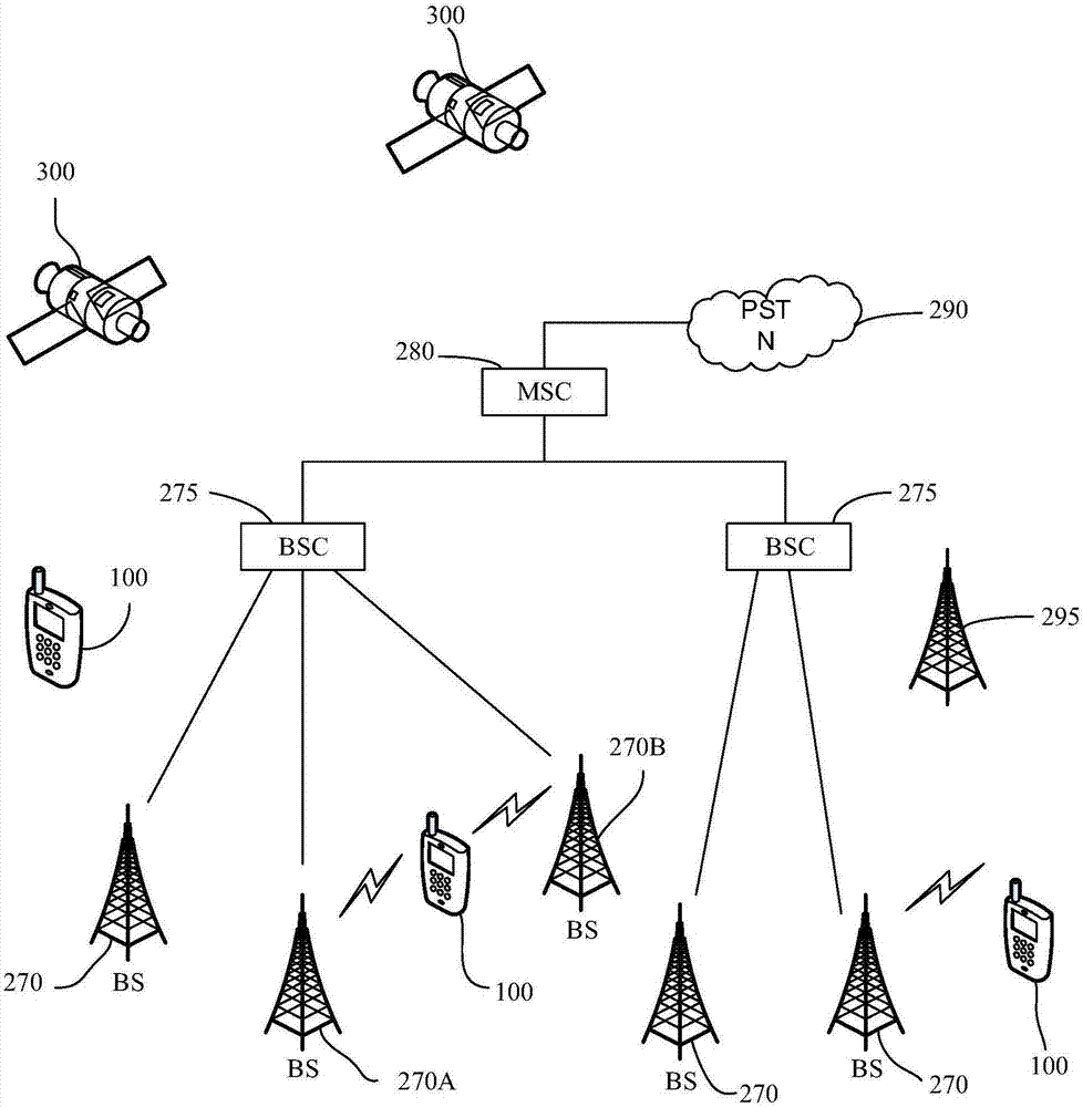
[0082] The above-mentioned fixed terminal may be a computer, etc., and the above-mentioned mobile terminal includes, but is not limited to, a mobile phone, a notebook computer, a camera, a PDA, a PAD, a PMP, a navigation device, and the like. The terminal may be connected to the Internet, wherein the connection may be through a mobile Internet network provided by an operator, or through a wireless access point for network connection.

[0083] Here, if the mobile terminal has an operating system, the operating system can be UNIX, Linux, Windows, Android (Android), Windows Phone and so on.

[0084] It should be noted that there is no limitation on the ...

no. 2 example

[0110] Figure 10 It is a flow chart of the second embodiment of the method for fingerprint identification using a terminal in the present invention, as shown in Figure 10 As shown, the process includes:

[0111] Step 1000: Preset N levels of reflected light signals, the levels of reflected light signals are in one-to-one correspondence with the transmitting power of the transmitter, and N is an integer greater than 1.

[0112] It can be understood that if each reflected optical signal corresponds to a different transmitter power, although the transmitter power can be set more accurately, the control accuracy of the transmitter can be improved. However, this setting method increases the processing process of the terminal and reduces the operating efficiency of the terminal.

[0113] It can be understood that when the transmission power is adjusted according to the light intensity of the reflected light signal, since the light intensity of the obtained reflected light signal...

no. 3 example

[0127] In order to better reflect the purpose of the present invention, further illustrations are made on the basis of the first embodiment of the present invention.

[0128] Figure 12 It is a flow chart of the third embodiment of the method for fingerprint identification using a terminal in the present invention, as shown in Figure 12 As shown, the process includes:

[0129] Step 1200: Adjust the transmitting power of the transmitter.

[0130] Here, for the method of adjusting the transmit power of the transmitter, reference may be made to the second embodiment of the present invention.

[0131] Step 1201: The terminal senses that the fingerprint recognition area is touched by the user.

[0132] Step 1202: Determine whether the area of ​​the current touch area is greater than or equal to the minimum fingerprint recognition area, if yes, execute step 1203; if not, return to step 1200.

[0133] In the embodiment of the present invention, the detector of the terminal may fur...


PUM


Abstract

The embodiments of the invention disclose a terminal used fingerprint identification method, a device and the terminal, wherein the terminal comprises at least one emitter. The emitter is used to transmit light signals to the fingerprint identification area of the terminal. The method comprises the following steps: obtaining the reflected light signals from the fingerprint identification area wherein the reflected light signals are light signals reflected from the fingerprint identification area after the at least one emitter transmits the light signals to the fingerprint identification area; determining the grades of the reflected light signals; according to the determined grades of the reflected light signal, determining the emission powers corresponding to the at least one emitter, wherein different grades of the reflected light signals corresponding to different emission powers; and obtaining the touch area of the fingerprint identification area touched by a user; controlling the emitter(s) that emit(s) reflected light signals to the touch area to emit light signals according to corresponding emission powers so as to execute the fingerprint identification operation. According to the invention, through the adjustment of the emission powers of the emitter(s), the fingerprint identification precision for a terminal is increased.

Description

technical field [0001] The present invention relates to the field of image processing, in particular to a method, device and terminal for fingerprint identification by using a terminal. Background technique [0002] At present, terminals with a fingerprint recognition function are becoming more and more popular, and fingerprint recognition is mostly used for operations such as unlocking, waking up, and paying for terminals. Among them, the fingerprint identification area of ​​the mobile terminal is mostly set directly below the touch panel of the mobile terminal (for example, the home button position on the front of the mobile phone). In order to expand the function of fingerprint identification and the convenience of operation, some mobile terminal manufacturers have begun to try Combining the fingerprint identification area of ​​the mobile terminal with the touch panel means embedding the fingerprint identification in the screen of the mobile terminal, for example: the "In...

Claims


Application Information

Patent Timeline
Patent Type & Authority Applications(China)
IPC IPC(8): G06K9/00H04M1/67
CPCH04M1/67G06V40/1318
Inventor 韩延罡
Owner 添津人工智能通用应用系统(天津)有限公司
Learn More