A hardware parts cutting device
A technology of parts and equipment, which is applied in the field of cutting equipment for hardware parts, can solve problems such as poor cutting effect, slow cutting speed, and heavy machines
- Summary
- Abstract
- Description
- Claims
- Application Information
AI Technical Summary
Problems solved by technology
Method used
Image
Examples
Embodiment 1
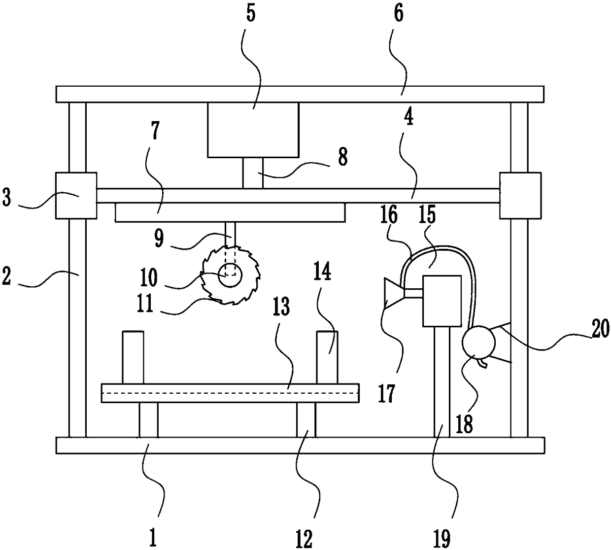
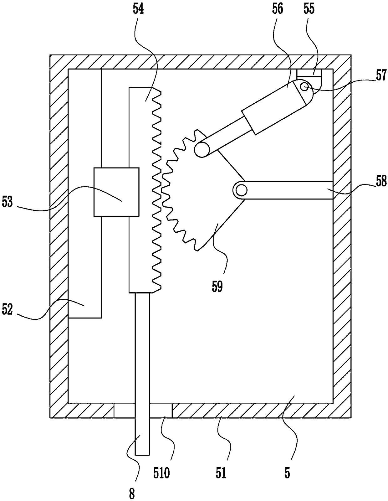
[0038] A kind of cutting equipment for hardware parts, such as Figure 1-Figure 7 As shown, it includes a bottom plate 1, a first guide rod 2, a first guide sleeve 3, a moving rod 4, a lifting device 5, a top plate 6, a moving device 7, a lifting rod 8, a mounting rod 9, a second motor 10, and a blade 11 , the first bracket 12, the placing table 13, the fixing device 14, the swinging device 15, the hose 16, the nozzle 17, the air pump 18, the first mounting plate 19 and the mounting seat 20, and the left and right sides of the bottom plate 1 are symmetrically welded with the first A guide rod 2, a top plate 6 is welded on the top of the two first guide rods 2, a lifting device 5 is arranged in the middle of the bottom of the top plate 6, a lifting rod 8 is connected to the bottom of the lifting device 5, and a moving rod 4 is welded at the bottom end of the lifting rod 8, The first guide rod 2 on the left side and the first guide rod 2 on the right side are all slidably connec...
Embodiment 2
[0040] A kind of cutting equipment for hardware parts, such as Figure 1-Figure 7 As shown, it includes a bottom plate 1, a first guide rod 2, a first guide sleeve 3, a moving rod 4, a lifting device 5, a top plate 6, a moving device 7, a lifting rod 8, a mounting rod 9, a second motor 10, and a blade 11 , the first bracket 12, the placing table 13, the fixing device 14, the swinging device 15, the hose 16, the nozzle 17, the air pump 18, the first mounting plate 19 and the mounting seat 20, and the left and right sides of the bottom plate 1 are symmetrically welded with the first A guide rod 2, a top plate 6 is welded on the top of the two first guide rods 2, a lifting device 5 is arranged in the middle of the bottom of the top plate 6, a lifting rod 8 is connected to the bottom of the lifting device 5, and a moving rod 4 is welded at the bottom end of the lifting rod 8, The first guide rod 2 on the left side and the first guide rod 2 on the right side are all slidably connec...
Embodiment 3
[0043] A kind of cutting equipment for hardware parts, such as Figure 1-Figure 7 As shown, it includes a bottom plate 1, a first guide rod 2, a first guide sleeve 3, a moving rod 4, a lifting device 5, a top plate 6, a moving device 7, a lifting rod 8, a mounting rod 9, a second motor 10, and a blade 11 , the first bracket 12, the placing table 13, the fixing device 14, the swinging device 15, the hose 16, the nozzle 17, the air pump 18, the first mounting plate 19 and the mounting seat 20, and the left and right sides of the bottom plate 1 are symmetrically welded with the first A guide rod 2, a top plate 6 is welded on the top of the two first guide rods 2, a lifting device 5 is arranged in the middle of the bottom of the top plate 6, a lifting rod 8 is connected to the bottom of the lifting device 5, and a moving rod 4 is welded at the bottom end of the lifting rod 8, The first guide rod 2 on the left side and the first guide rod 2 on the right side are all slidably connec...
PUM
 Abstract
Description
Claims
Application Information
 - R&D
- Intellectual Property
- Life Sciences
- Materials
- Tech Scout
- Unparalleled Data Quality
- Higher Quality Content
- 60% Fewer Hallucinations
Browse by: Latest US Patents, China's latest patents, Technical Efficacy Thesaurus, Application Domain, Technology Topic, Popular Technical Reports.
© 2025 PatSnap. All rights reserved.Legal|Privacy policy|Modern Slavery Act Transparency Statement|Sitemap|About US| Contact US: help@patsnap.com


