
Method for assessing residual intensities of composite material structures with low-speed impact damage

A low-velocity impact damage and composite material technology, applied in special data processing applications, instruments, electrical digital data processing, etc., can solve the problem of not being able to truly reflect material damage, process discontinuity, and affecting the accuracy of residual strength calculations, etc. question

Inactive Publication Date: 2017-08-25
NANJING UNIV OF AERONAUTICS & ASTRONAUTICS
View PDF2 Cites 20 Cited by
  • Summary
  • Abstract
  • Description
  • Claims
  • Application Information

AI Technical Summary

Problems solved by technology

[0008] 1. Both are only suitable for solving the problem of uniform laminates of equal thickness, and there are limitations in solving the residual strength problems of complex structures such as reinforced wall panels with impact damage and variable thickness panels
[0009] 2. The finite element model involved in the above method does not reflect the damage of the material well
This approximate equivalent treatment method leads to the fact that the material parameters input by the finite element model cannot truly reflect the material properties after impact
Therefore, the impact on the residual strength calculation results is: on the one hand, this finite element simulation method does not include the impact process, and the whole process is discontinuous; on the other hand, it cannot truly reflect the impact damage state of the structure, which affects the accuracy of the residual strength calculation

Method used


Image

  • Method for assessing residual intensities of composite material structures with low-speed impact damage
  • Method for assessing residual intensities of composite material structures with low-speed impact damage
  • Method for assessing residual intensities of composite material structures with low-speed impact damage

Examples


Embodiment Construction

[0032] The present invention will be further described in detail below in conjunction with the drawings and specific preferred embodiments.

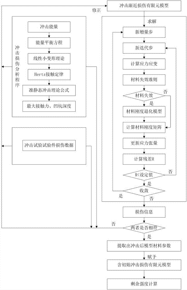
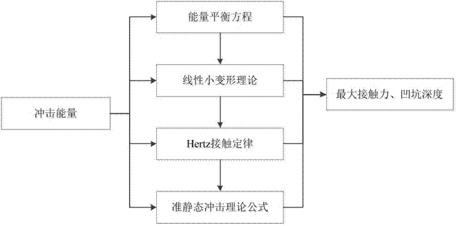
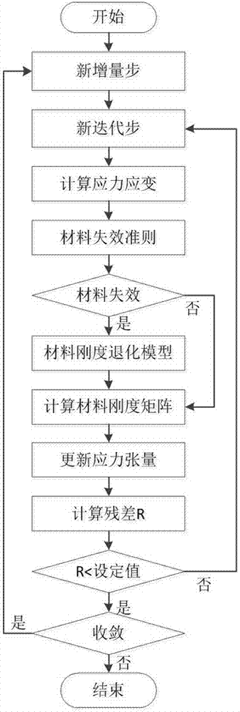
[0033] Such as figure 1 As shown, a method for evaluating the residual strength of a composite material structure containing low-velocity impact damage includes the following 6 steps.

[0034] Step 1. Low-speed impact test.

[0035] For multiple identical test pieces, conduct impact tests under different large impact energies, and use non-destructive testing methods to detect impact damage caused by large impact energy, and record the damage characteristic parameter 1. Then, according to the low-speed impact test results, The curve relationship between impact energy and damage characteristic parameter one is obtained.

[0036] Among them, the above-mentioned damage characteristic parameter one includes pit diameter, pit depth and delamination damage area, etc.; the above-mentioned large impact energy means that the impact damage size generated b...


PUM


Abstract

The invention discloses a method for assessing residual intensities of composite material structures with low-speed impact damage. The method comprises six steps of: 1, obtaining a curve relationship between impact energy and damage characteristic parameters through low-speed impact test results; 2, obtaining a maximum contact force and a maximum pit depth under corresponding impact energy by adoption of an impact damage theory; 3, establishing a low-speed impact progressive damage finite element model; 4, correcting the low-speed impact progressive damage finite element model; 5, establishing a residual intensity finite element model with impact damage; and 6, solving the residual intensity finite element model with the impact damage to obtain a residual intensity value. According to the method disclosed by the invention, finite element simulation is applied to impact damage models, and the impact test results and the impact damage theory are combined, so that the accurate simulation for damage states, the accurate building of finite element models with initial impact damage and the continuity of assessment processes are realized, and a relatively high practical value is provided.

Description

Technical field [0001] The invention relates to composite material technology, in particular to a method for evaluating the residual strength of a composite material structure containing low-speed impact damage. Background technique [0002] The literature [林智育,许希武.Remaining compressive strength of composite laminates after low-velocity impact[J].Journal of Composites,2008,25(1):140-146.] summarizes the current research on composite structures with initial damage There are several common methods for solving residual strength. These practices include: [0003] (1) The softening inclusion method, which equates the impact damage on the composite structure to a regular-shaped softening inclusion, and then uses point stress or average stress criteria based on various failure criteria to determine the failure strength of the plate. [0004] (2) The sub-layer buckling method regards impact damage as multiple regular-shaped layers of different sizes. It is considered that the compression f...

Claims


Application Information

Patent Timeline
IPC IPC(8): G06F17/50
CPCG06F30/23G06F2119/06
Inventor 陆晓华邵传金左洪福徐瑀童
Owner NANJING UNIV OF AERONAUTICS & ASTRONAUTICS
Learn More