
Light field camera with compact structure

A light field camera with a compact structure, applied in the optical field, can solve the problems of large size, difficult installation, and complex structure of the camera, and achieve the effects of ensuring imaging effect, reducing volume, and improving assembly efficiency

Pending Publication Date: 2017-08-18
SHENZHEN ORBBEC
View PDF4 Cites 9 Cited by
  • Summary
  • Abstract
  • Description
  • Claims
  • Application Information

AI Technical Summary

Problems solved by technology

[0004] The purpose of the embodiments of the present invention is to provide a light field camera with a compact structure to solve the technical problems in the prior art that the camera is large in size, complex in structure and difficult to install

Method used


Image

  • Light field camera with compact structure
  • Light field camera with compact structure

Examples


Embodiment Construction

[0020] In order to make the technical problems, technical solutions and beneficial effects to be solved by the embodiments of the present invention clearer, the present invention will be further described in detail below in conjunction with the accompanying drawings and embodiments. It should be understood that the specific embodiments described here are only used to explain the present invention, not to limit the present invention.

[0021] It should be noted that when an element is referred to as being “fixed” or “disposed on” another element, it may be directly on the other element or be indirectly on the other element. When an element is referred to as being "connected to" another element, it can be directly connected to the other element or indirectly connected to the other element.

[0022] It is to be understood that the terms "length", "width", "top", "bottom", "front", "rear", "left", "right", "vertical", "horizontal", "top" , "bottom", "inner", "outer" and other ind...


PUM


Abstract

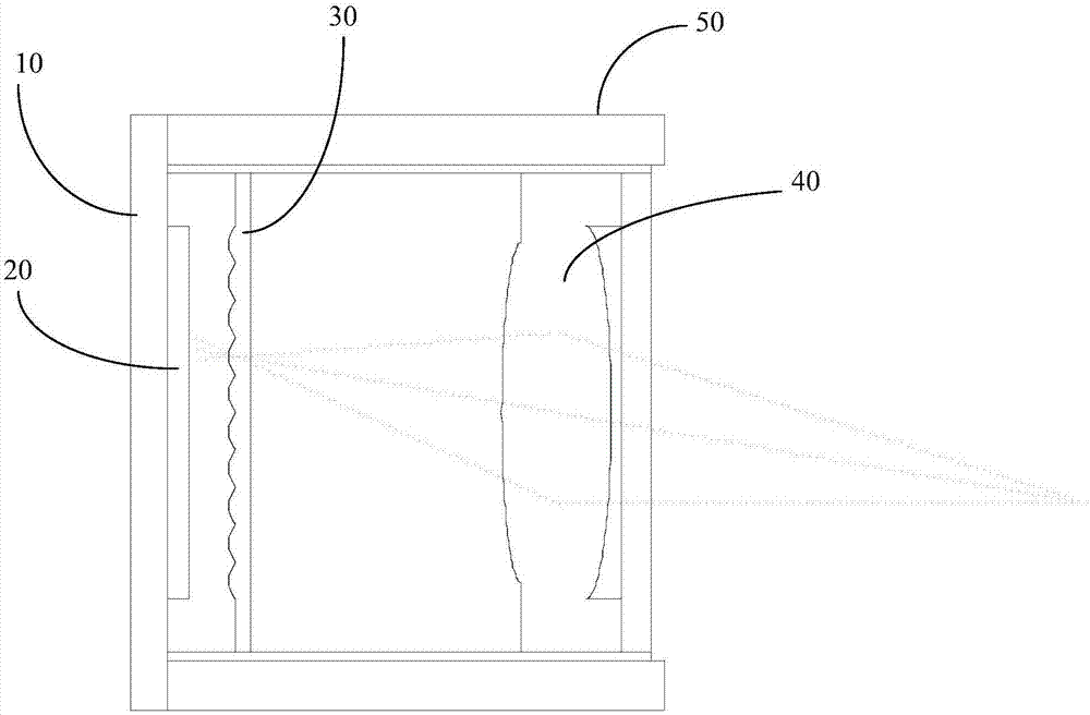
The invention provides a light field camera with a compact structure. The optical field camera comprises, in sequence, a base; an image sensor which is arranged on the base; a microlens array which is arranged at a light incident side of the image sensor and comprises a plurality of microlens units arranged in an array mode, wherein each microlens unit correspond to a plurality of photosensitive units on the image sensor; a master lens which is arranged at the light incident side of the microlens array and is used for receiving light of a to-be-imaged object and projecting the light to the microlens array; a lens cone which is arranged on the base and is used for fixing the master lens and the microlens array; an infrared cut-off light filter which is adhered on a surface of the microlens array backing on to the image sensor; and anti-reflection film which is adhered on the surface of the microlens array facing or backing on to the image sensor. The infrared cut-off light filter and the anti-reflection film are respectively adhered on the surfaces of the microlens array, so an area of the light field camera is reduced. Assembly of the camera is convenient, so the assembly efficiency is improved. The stability of optical elements is improved. An imaging effect is ensured. The quality of the camera is improved.

Description

technical field [0001] The invention belongs to the field of optical technology, and more specifically relates to a compact light field camera. Background technique [0002] Compared with traditional cameras, light field cameras can not only obtain the intensity of light but also the direction of light, which makes light field cameras have more functions, such as taking pictures first and then focusing, large depth of field imaging, 3D imaging and perspective imaging etc. The more widely used structure in light field cameras is based on the microlens array (MLA) structure, that is, by arranging an MLA array between the photosensitive chip and the imaging lens, each MLA array unit corresponds to pixels on multiple photosensitive chips, Through the MLA unit, the target light originally focused on one point can be imaged on the corresponding pixels of the unit at different angles through the MLA unit, and the above-mentioned various functions can be realized by processing thes...

Claims


Application Information

Patent Timeline
IPC IPC(8): H04N5/225G03B17/12
CPCG03B17/12H04N23/54H04N23/55
Inventor 黄杰凡许星
Owner SHENZHEN ORBBEC
Learn More