
Spherical cage and spherical shell structure and technological processing method thereof

A technology of spherical shell structure and treatment method, applied in heat treatment furnaces, heat treatment equipment, metal material coating processes, etc., can solve the problems of inconsistent phase transition temperature, performance degradation of mechanical parts, automobile suffering, etc., to ensure ductility and hardness. requirements, high and low temperature impact toughness, and the effect of avoiding impact energy reduction

Pending Publication Date: 2017-08-18
NINGBO V SHINE AUTO PARTS
View PDF6 Cites 0 Cited by
  • Summary
  • Abstract
  • Description
  • Claims
  • Application Information

AI Technical Summary

Problems solved by technology

The disadvantage of the existing spherical cage and spherical shell structure is that the internal structure of the entire shell is unreasonable, which causes the car to suffer during the steering process, and brings certain safety hazards during the driving process. At the same time, due to improper processing methods during the process It will lead to a decrease in the performance of mechanical parts and the existing technology is difficult to control and realize. Due to the different volume densities of upper bainite and pearlite, the phase transition temperature is inconsistent during induction hardening heating, and the volume thermal expansion is different during phase transition, resulting in the tendency of intermediate frequency induction hardening cracks sex increase

Method used


Image

  • Spherical cage and spherical shell structure and technological processing method thereof
  • Spherical cage and spherical shell structure and technological processing method thereof
  • Spherical cage and spherical shell structure and technological processing method thereof

Examples


Embodiment Construction

[0022] The following are specific embodiments of the present invention and in conjunction with the accompanying drawings, the technical solutions of the present invention are further described, but the present invention is not limited to these embodiments.

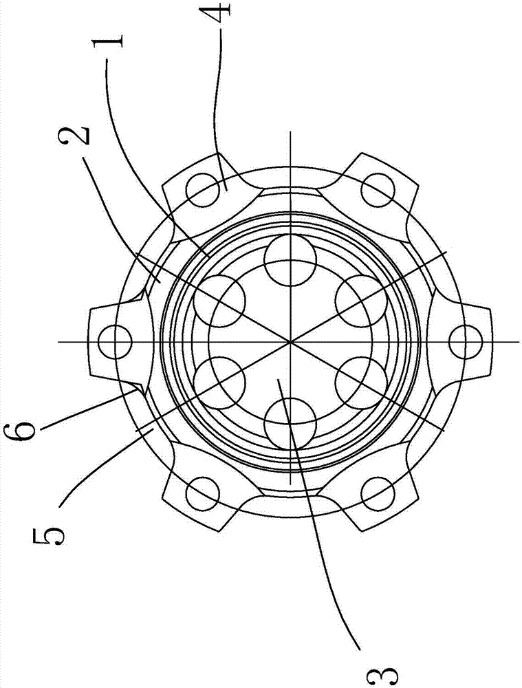
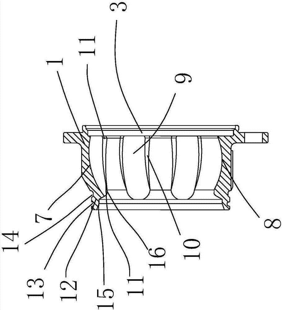
[0023] In the figure, the main shell 1; the outer frame body 2; the inner space body 3; the angled body 4; the outer rotation arc notch 5; Matching part 9; channel 10; channel chamfer 11; main body part 12; clamp first groove 13; clamp second groove 14;

[0024] Such as figure 1 and figure 2 As shown, the spherical shell structure of the ball cage includes a main housing 1, the main housing 1 is divided into an outer frame body 2 and an inner space body 3, steel balls are arranged in the inner space body 3, and on the surface of the outer frame body 2 There are six corners 4 along the circumference of the main housing 1, and there is an outwardly turning arc-shaped gap 5 between the two corners 4, and there is a buffer ...


PUM


Abstract

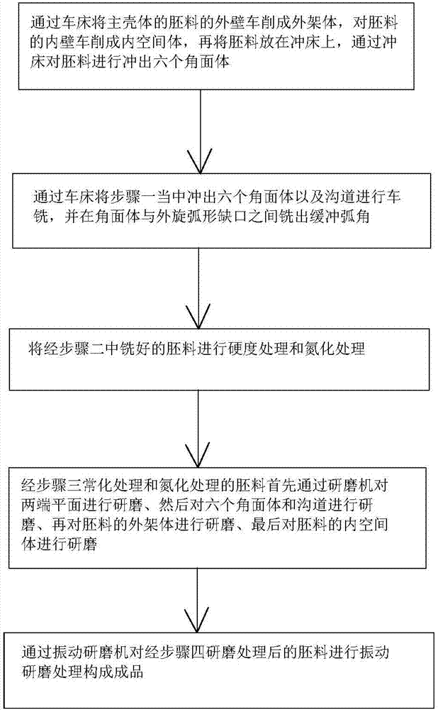
The invention belongs to the technical field of automobile drive accessories, and provides a spherical cage and spherical shell structure and a technological processing method thereof. The spherical cage and spherical shell structure comprises a main shell. The main shell is divided into an outer frame body and an inner space body. A steel ball is arranged in the inner space body. Six edged surface bodies are arranged on the surface of the outer frame body along the circumferential face of the main shell. An outward-rotation arc-shaped notch is formed between every two adjacent edged surface bodies. The hardness of the outer frame body and the inner space body which are subjected to technological processing reaches the Rockwell hardness being 58-62. The outer wall of a blank of the main shell is subjected to turning through a lathe to form the outer frame body, the inner wall of the blank is subjected to turning to form the inner space body, then, the blank is put on a punching machine, punching is conducted on the blank through the punching machine to form the six edged surface bodies, and hardness treatment and nitrogen treatment are conducted on the milled blank. The spherical cage and spherical shell structure and the technological processing method have the beneficial effects that by means of the channel chamfering angle, it can be ensured that the steel ball is at the center position as much as possible when the steel ball rotates, the bearing capacity is improved, and the hardness is regulated to 20-26 HRC. Therefore, the ductility and hardness requirement of a whole spherical cage and spherical shell is ensured.

Description

technical field [0001] The invention belongs to the technical field of automobile drive accessories, and relates to a spherical cage and spherical shell structure and a processing method thereof. Background technique [0002] In order to transmit the power of the car, the drive axle assembly will be used. At present, the ball cage type drive axle assembly is the most used. Speed ​​transmission problem, and the transmission working angle is large and the efficiency is high. The disadvantage of the existing spherical cage and spherical shell structure is that the internal structure of the entire shell is unreasonable, which causes the car to suffer during the steering process, and brings certain safety hazards during the driving process. At the same time, due to improper processing methods during the process It will lead to a decrease in the performance of mechanical parts and the existing technology is difficult to control and realize. Due to the different volume densities o...

Claims


Application Information

Patent Timeline
IPC IPC(8): F16D3/22B23P15/14C21D1/25C21D9/00C22C38/02C22C38/04C22C38/42C22C38/44C22C38/46C23C8/34
CPCF16D3/22C21D1/25C21D9/0068C22C38/02C22C38/04C22C38/42C22C38/44C22C38/46C23C8/34B23P15/14F16D2200/0021F16D2300/10C21D2211/002C21D2211/009
Inventor 叶祥宝
Owner NINGBO V SHINE AUTO PARTS
Learn More