
Quenching treatment device for machining of aluminum strips

A technology of processing device and aluminum strip, applied in quenching device, heat treatment furnace, heat treatment equipment and other directions, can solve the problems of affecting the coiling quality of aluminum strip, waste of quenching liquid, etc., and achieve novel design, improve coiling quality, and avoid waste. Effect

Inactive Publication Date: 2017-08-18
张子和
View PDF7 Cites 1 Cited by
  • Summary
  • Abstract
  • Description
  • Claims
  • Application Information

AI Technical Summary

Problems solved by technology

[0003] In order to increase the mechanical strength of the aluminum strip during use, it is necessary to quench the aluminum strip. The existing aluminum strip quenching treatment is to cool the aluminum strip by spraying quenching liquid in the quenching box. In order to increase the cooling speed, the aluminum strip is now Immersed in the quenching liquid and sprayed with quenching liquid to cool, this cooling method has a fast cooling speed and good cooling effect, but in the actual quenching process, it will cause the aluminum strip to avoid a large amount of quenching liquid on the surface, which will not only affect the later aluminum The winding quality of the belt also causes a lot of waste of quenching liquid

Method used


Image

  • Quenching treatment device for machining of aluminum strips
  • Quenching treatment device for machining of aluminum strips
  • Quenching treatment device for machining of aluminum strips

Examples


Embodiment Construction

[0020] It should be noted that, in the case of no conflict, the embodiments of the present invention and the features in the embodiments can be combined with each other.

[0021] In describing the present invention, it should be understood that the terms "center", "longitudinal", "transverse", "upper", "lower", "front", "rear", "left", "right", " The orientations or positional relationships indicated by "vertical", "horizontal", "top", "bottom", "inner" and "outer" are based on the orientations or positional relationships shown in the drawings, and are only for the convenience of describing the present invention and Simplified descriptions, rather than indicating or implying that the device or element referred to must have a particular orientation, be constructed and operate in a particular orientation, and thus should not be construed as limiting the invention. In addition, the terms "first", "second", etc. are used for descriptive purposes only, and should not be understood ...


PUM


Abstract

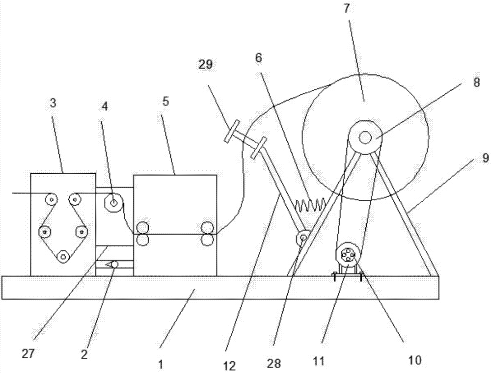
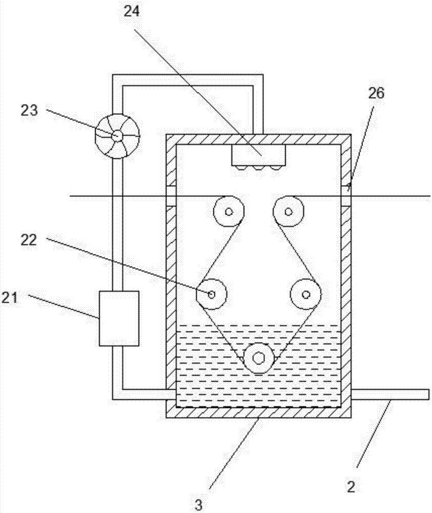
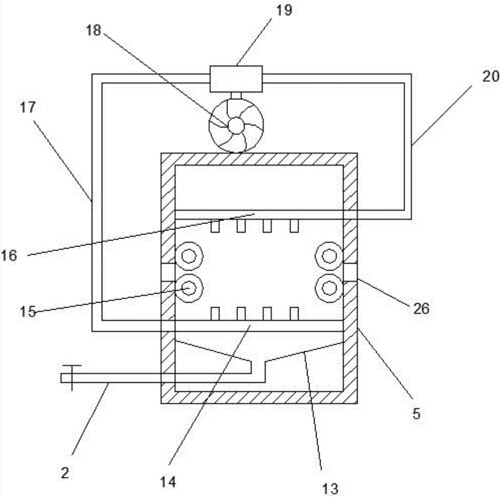
The invention discloses a quenching treatment device for machining of aluminum strips. The quenching treatment device comprises a base. The upper side of the left end of the base is connected with a quenching box. A liquid injection port is connected to the interior of the top end of the quenching box. The upper end of the liquid injection port is connected with a liquid guide pump. The lower end of the liquid guide pump is connected with a refrigerating device. The middle of the upper end of the base is connected with a drying box. An induced draft fan is fixed to the top end of the drying box. The upper end of the induced draft fan is connected with a flow divider valve. The right end of the flow divider valve is connected with a wind feed pipe. The lower end of the wind feed pipe is connected with a wind feed plate. The left end of the flow divider valve is connected with a wind discharge pipe. The lower end of the wind discharge pipe is connected with a wind discharge plate. The right side of the upper end of the base is connected with a supporting frame. The upper end of the supporting frame is provided with a winding wheel. The middle of the winding wheel is coaxially connected with a driven belt pulley. The lower end of the driven belt pulley is connected with a driving belt pulley through a belt. The middle of the driving belt pulley is connected with a driving motor. By adopting the quenching treatment device for machining of the aluminum strips, drying treatment of quenched aluminum strips is realized; and meanwhile, cyclic utilization of quenching liquid is realized, and waste of quenching liquid is avoided.

Description

technical field [0001] The invention relates to the technical field of aluminum industry processing, in particular to a quenching treatment device for aluminum strip processing. Background technique [0002] Aluminum strip (Aluminumstrip / Aluminumstrip) raw materials are pure aluminum or aluminum alloy cast-rolled aluminum coils, hot-rolled aluminum coils, which are rolled into thin-plate aluminum coils of different thicknesses and widths by cold rolling mills, and then longitudinally Slit into aluminum strips of different widths. The specific uses of aluminum strips mainly include: aluminum strips for transformers (transformer aluminum foil), aluminum strips for high-frequency welding hollow aluminum strips, aluminum strips for fin radiators, aluminum strips for cables, aluminum strips for stamping, aluminum strips for aluminum edge strips, etc. [0003] In order to increase the mechanical strength of the aluminum strip during use, it is necessary to quench the aluminum str...

Claims


Application Information

Patent Timeline
Patent Type & Authority Applications(China)
IPC IPC(8): C21D1/64C21D1/667C21D9/573C22F1/04
CPCC21D1/64C21D1/667C21D9/5737C22F1/04Y02P10/20
Inventor 张子和
Owner 张子和
Learn More