Eureka AIR delivers breakthrough ideas for toughest innovation challenges, trusted by R&D personnel around the world.

Integral waveguide cavity division machining method

A waveguide cavity and waveguide technology, which is applied in the field of integral waveguide cavity subdivision processing, can solve the problems of difficult finishing, increased manufacturing cost, and increased production cycle, so as to improve detection sensitivity and detection distance, and reduce processing technology skills Requirements, the effect of saving processing man-hours

Inactive Publication Date: 2017-08-18
CNGC INST NO 206 OF CHINA ARMS IND GRP
View PDF8 Cites 2 Cited by
  • Summary
  • Abstract
  • Description
  • Claims
  • Application Information

AI Technical Summary

Problems solved by technology

[0008] 2) The material has high plasticity and difficult finishing;
The cavity design of millimeter wave components requires strict symmetry and coaxiality. The design basis is mostly the geometric center of the waveguide cavity. In most cases, due to the limitation of processing technology, the center positioning cannot be used for clamping, and only the outer surface can be used. These indirect machining benchmarks are used for positioning and clamping, and this clamping method has errors relative to the design benchmarks
In addition, due to the large number of processing parts, multi-step and multi-process processing are required, and it is difficult to maintain consistent benchmarks, which will lead to poor part processing reliability, low production efficiency, unstable quality and low yield
[0012] 4) The integrity requirements of the waveguide cavity are high
In order to ensure the integrity of the cavity, it is often necessary to use special processing equipment such as EDM and wire cutting. It is necessary to make different electrodes and clamping tools for different cavities, which increases the production cycle and increases the manufacturing cost.

Method used

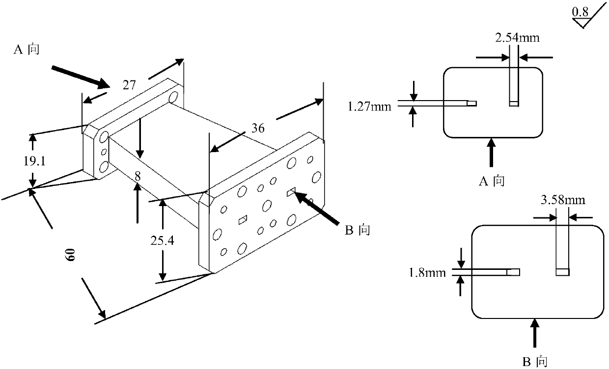
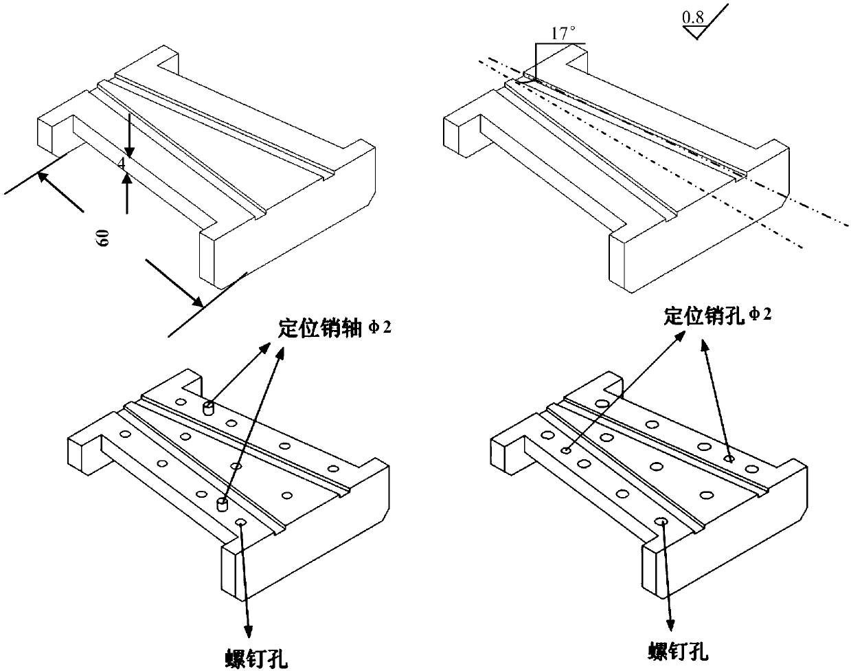
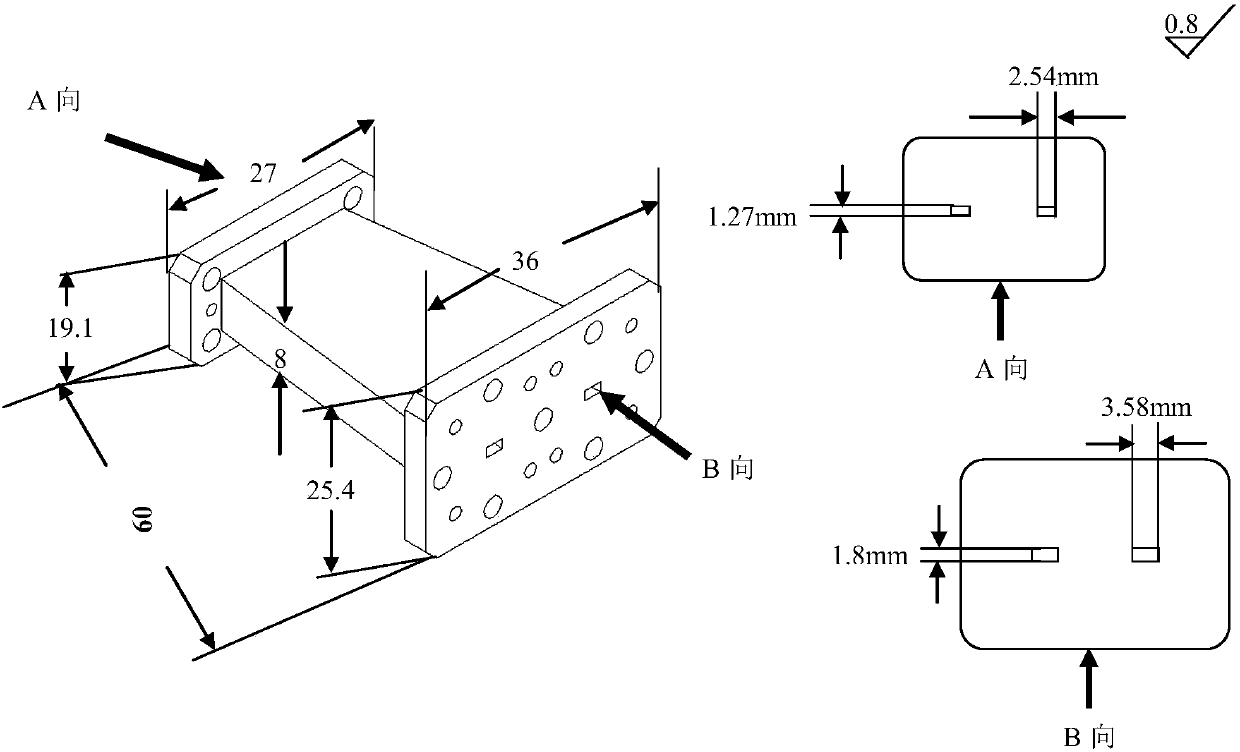

Image

  • Integral waveguide cavity division machining method
  • Integral waveguide cavity division machining method
  • Integral waveguide cavity division machining method

Examples


Embodiment Construction

[0044] Now in conjunction with embodiment, accompanying drawing, the present invention will be further described:

[0045] The following problems must be solved when processing the inner cavity of the millimeter-wave radar waveguide cavity: it is necessary to meet the final machining accuracy and surface roughness of the millimeter-wave radar waveguide cavity, that is, the machining accuracy of the inner cavity of the millimeter-wave radar waveguide cavity is ±0.01mm , the surface roughness of the inner cavity of the millimeter-wave radar waveguide cavity is 0.8 μm, and at the same time, it must be ensured that the processing method selected in the present invention can complete the processing with high quality and quantity, and high efficiency. The technical method adopted in the present invention is: the original integral millimeter-wave radar waveguide cavity is symmetrically cut, so that the processing accuracy and processing quality problems that cannot be solved by the or...


PUM


Abstract

The invention relates to an integral waveguide cavity division machining method. According to the method, during machining, an integral structure is firstly divided according to machining features, then multiple divided parts obtained through machining are precisely matched and assembled by pin shafts through locating pin holes in the pin shafts, and the ideal integral waveguide cavity part method is obtained.

Description

technical field [0001] The invention belongs to the technical field of precision machinery manufacturing, relates to the field of integral waveguide cavity processing, in particular to a method for splitting and processing the integral waveguide cavity. In the processing, the overall structure is first divided according to the processing characteristics, and then the pin shafts are used to precisely fit and assemble the processed several divided parts through the positioning pin holes on them to obtain an ideal integral waveguide cavity part. method. Background technique [0002] Millimeter wave radar is currently widely used in many aspects such as guidance, strategy, tactical communication, and electronic countermeasures. Components, the millimeter-wave radar waveguide cavity covers a wide range of types and has a variety of composition forms, and the waveguide cavity itself is required to have high thermal conductivity, high electrical conductivity and high sealing perfo...

Claims


Application Information

Patent Timeline
Patent Type & Authority Applications(China)
IPC IPC(8): B23P15/00
CPCB23P15/00
Inventor 汪云虎霍龙军贺小红田倩傅强施剑波杨莉王拓桑多鹏毕思雯
Owner CNGC INST NO 206 OF CHINA ARMS IND GRP
Why Eureka
Eureka Blog
Learn More